Theory of operation – Elecraft KPA500 Owner's Manual User Manual
Page 25
25
Theory of Operation
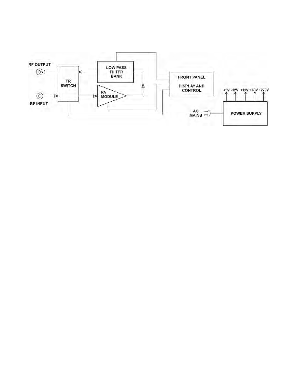
When the KPA500 is in operating (OPER) mode, RF is routed by the transmit-receive (TR) switch to the power
amplifier (PA) module where it is amplified by a pair of VRF2933 FETs.
The PA module output is routed to the low pass filter (LPF) bank input. The LPF bank provides filters for each
frequency band. The frequency of the incoming signal is monitored and the appropriate filter is automatically
switched into the signal path. The filter also may be selected by band data provided by the transceiver or by
front panel switches on the KPA500. However, the automatic selection based on the incoming signal frequency
overrides either of those inputs to ensure the correct bandpass filter is always in the signal path.
The output of the LPF bank is routed to the RF output via the TR switch.
During receive or when the KPA500 is in Standby (STBY), the TR switch routes the RF input directly to the RF
output, bypassing both the PA module and the low pass filter bank.
The MCU in the display and control module monitors and makes critical measurements of a number of
operating conditions including two levels of fault conditions that automatically alter the operation of the
KPA500 (see pg 19).