Monitoring, Remote operation – Elecraft KPA500 Owner's Manual User Manual
Page 18
18
Monitoring
KPA500 operation is monitored by the LEDs
,
and
and reported in text on the LCD.
LEDs
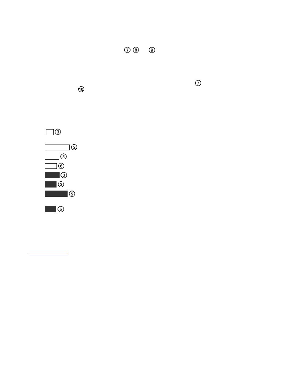
The SWR of the load and the output power are displayed on LED bar graphs. The bar graphs are color-coded:
green for normal operating range, yellow for marginal levels and red for excessive levels. Excessive levels may
trigger a fault and shut the KPA500 off (see Fault Conditions below). An LED
lights if a fault condition
occurs. Also two LEDs
indicate whether the amplifier is in standby (
STBY
) or operating (
OPER
) mode.
LCD
Normally the LCD displays the band currently selected. The four switches around the LCD select other
information to be displayed on the screen and the behavior of the LEDs. Note that these switches have both tap
and hold functions (pg 3). Repeat the tap or hold action to return the LCD to the band display.
H V
displays the PA voltage on the LCD. Must be between 65 and 85 V when the KPA500 is in
STBY.
C U R R E N T
displays the PA current on the LCD. Must never exceed 20 A.
T E M P
displays the heat sink temperature on the LCD. Must be less than 90C.
P W R
displays the output power numerically on the LCD. Must not exceed 650 W.
M E N U
displays the menu system (see pg. 20).
E D I T
enables editing menu parameters (see pg. 20).
P K H O L D
toggles the peak power output display on the bar graph. When enabled, the LED
corresponding to the peak power output remains lighted for one second.
S W R
displays the load SWR numerically on the LCD.
Remote Operation
The KPA500 can be controlled remotely using a personal computer connected to the RS232 port. A basic
remote operating capability is built into the KPA500 Utility program (see pg 21). For those who may wish to
develop their own software, a Command Reference Manual is available on the Elecraft web site.
(
www.elecraft.com
).