Elecraft KAT2 User Manual
Page 7
7
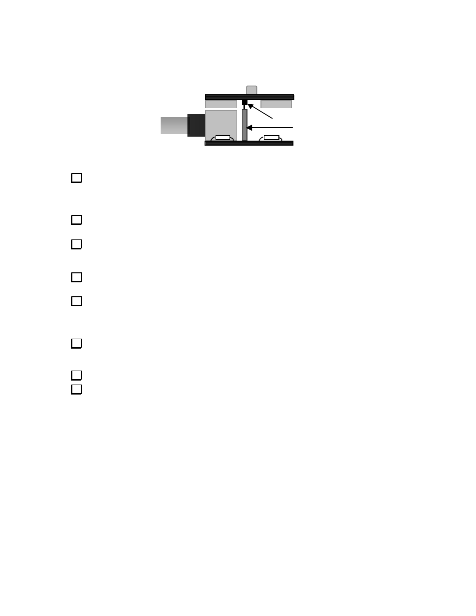
Refer to the drawing below during the following steps. This left end view shows how the L-C and
Control boards will appear when connected together. Relays K1 and K2 can be seen on the bottom of the
L-C board, along with 16-pin male connector P4. On the control board, J2 (BNC), R5, and R6 are visible,
as well as 16-pin female connector J4. The 13/16" standoffs are omitted for clarity.
J4
P4
L-C
Control
Locate the two 16-pin male connectors, P4 and P5. These connectors must be installed on the bottom
of the L-C board, between the two rows of relays (see above). Do not solder all pins of P4 and P5 at this
time. Instead, position the connectors, then solder only pins 1 and 16 on each connector. Make sure the
connectors are perpendicular to the board.
Install the two 16-pin female connectors, J4 and J5, on the top of the Control board as shown above.
Solder only pins 1 and 16 of each connector. Make sure the connectors are perpendicular to the board.
Plug the L-C board into the Control board as shown, mating P4 with J4 and P5 with J5. Be very
careful to avoid bending any pins on P4 and P5. Once the boards are properly mated, secure the L–C board
to the Control board standoffs temporarily using two 4-40 screws.
Press the two boards tightly together at both ends and in the middle. Once the 16-pin connectors
appear to be perpendicular to the boards and seated completely flat, solder all pins of P4, P5, J4, and J5.
Remove the screws holding the L-C board to the two standoffs. Then unplug the L-C board from the
Control board using the following method: Using a small screwdriver or Allen wrench, pry P4 upwards a
small amount, then pry P5 upwards a small amount, repeating this until the L-C board can be easily
unplugged. Do not pull the boards apart directly, as this may bend pins on P4 and P5.
Some pins on the bottom of the Control board must be trimmed to prevent shorting to the
K160RX option module. Trim the pins of the following components: E1, J5, C45, C46, C47, and J1
(signal pins only, not the large ground posts).
Carefully examine the entire ATU Control board for solder splashes or unsoldered pins (both sides).
Install C36 on the L-C board (.001 µF, "102").