Elecraft KAT2 User Manual
Page 5
5
Install BNC jacks J1 and J2. These connectors must be seated flat on the PC board and aligned
with the board's edge to allow for proper installation in the top cover. Solder one of the alignment pins
first, then re-heat the connection while pressing down on the jack. Once you're sure the connector is seated
correctly, solder the other pins.
Install screw terminal E1. (If E1 was supplied with a screw, remove it. The screw will not be used.)
Like J1 and J2, this component's alignment is critical. Use the same mounting technique.
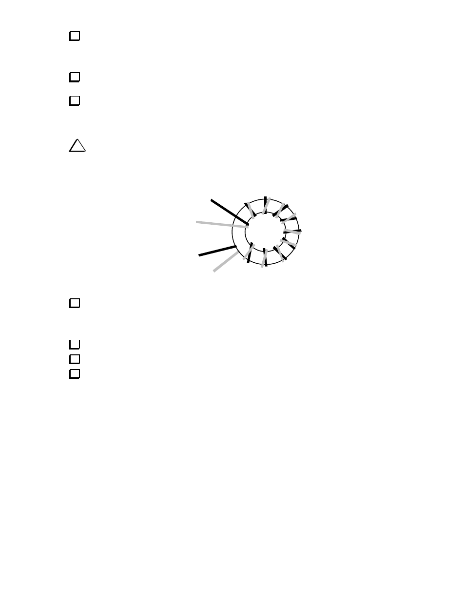
Transformer T1 is wound on a dark gray toroidal core (ferrite, 3/8" [9 mm] diameter). Cut two 10"
(25 cm) lengths of #26 enamel wire, one red and one green. Twist the two wires together loosely, crossing
over each other about 2 to 3 times per inch (once per cm). Then wind the twisted wires onto the core as
shown below, using 10 turns. Each pass through the core counts as one turn.
i
T1
must be wound exactly as shown, with leads 1 and 3 emerging from the back side of
the core and leads 2 and 4 from the front side.
1 (RED)
3 (GRN)
2 (RED)
4 (GRN)
Trim the leads of T1 to about 1/2" (12 mm) long. Completely remove the insulation from T1's leads
up to the edge of the core, using a solder pot or hot soldering iron tip. Do not attempt to burn off the
insulation using a match or lighter, as the flame may fuse the pairs of wire together, causing them to
become shorted. Another way to remove the insulation is to use fine sand paper.
Tin T1's leads with solder. If the leads do not tin easily, the insulation may not be fully removed.
Using an ohmmeter, measure between the red and green wires to make sure that they're not shorted.
Install T1 as indicated by its PC board outline near the right end of the board. Insert the leads into the
numbered holes as shown by the drawing of T1, above. Pull the leads taut on the bottom of the board.
Before soldering, use a magnifying glass to make sure that the entire portion of exposed lead is properly
tinned.