23 circuit details, kat2 l-c board, L-c board schematic – Elecraft KAT2 User Manual
Page 23
23
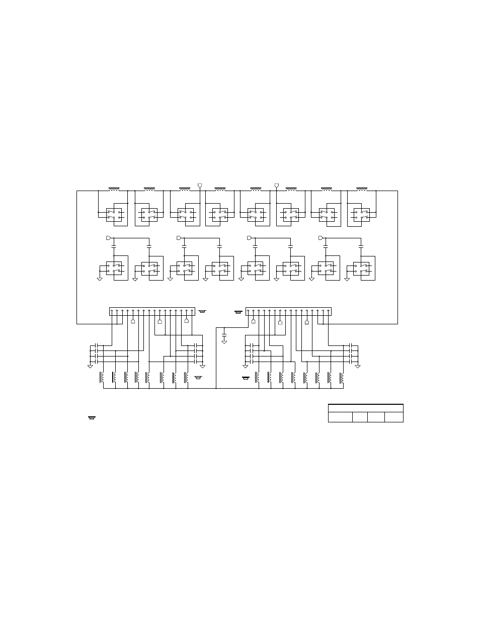
Circuit Details, KAT2 L-C Board
The L-C board provides eight series inductors and eight parallel capacitors, configured as an L-network. The
capacitance can be placed at the transmitter or antenna end of the network via a relay on the Control board (see next
page). Each inductor and capacitor has its own DPDT relay, with the individual sections of each relay placed in parallel
for reliability. The relays are selected under control of the ATU's microcontroller. Latching relays are used so that they
will not consume any power except when the operator is actually tuning. The relays are switched one at a time to keep
switching current low and to provide acoustically and electrically quiet operation. This results in somewhat longer tune
times.
For additional reliability, the connectors used between the L-C and control boards have gold-plated contacts, and
redundant pins are used for RF signals. Bypass capacitors are used on relay control lines to prevent RF signals from
reaching the microcontroller.
L-C Board Schematic
L8 is wound on T50-1 core (blue). All others are wound on T50-2 core (red).
= On bottom of PC board. All relays on the L-C board are on the bottom.
RELAY COMMON
W. Burdick
E. Swartz
L-NET OUT
Elecraft
L-NET IN
10.4 µH
.64 µH
1.3 µH
2.6 µH
5.2 µH
Rev. Sht.
.08µH
.16µH
.32µH
Date
1200
.001
.001
.001
.001
.001
C1_2
C3_4
C5_6
C7_8
C
7_8
C
3_4
C
5_6
C
1_2
K12
K15
K16
K13
K14
K10
K11
K10
K11
K12
K13
K14
K15
K16
150
300
620
C20
C23
C22
C21
C24
C25
C26
C27
C31
C32
C33
C34
C35
C36
C37
C38
C42
K5
K6
K7
K8
P4
P5
By
10
K1
10
10
K2
10
K4
10
10
K9
10
K3
10
10
10
10
10
10
10
10
10
10
11
12
13
14
15
16
10
11
12
13
14
15
16
L1
L2
K2
L3
L4
K4
L5
L6
K6
L7
L8
K8
K9
C1
C2
C3
C4
C5
C6
C7
C8
10
22
39
82
K1
K3
K5
K7
1
1
1
1
1
1
1
1
1
1
1
1
1
1
1
1
2
4
3
9
7
8
2
4
3
9
7
8
2
4
3
9
7
8
2
4
3
9
7
8
2
4
3
9
7
8
2
4
3
9
7
8
2
4
3
9
7
8
2
4
3
9
7
8
2
4
3
9
7
8
2
4
3
9
7
8
2
4
3
9
7
8
2
4
3
9
7
8
1
2
3
4
5
6
7
8
9
1
2
3
4
5
6
7
8
9
2
4
3
9
7
8
2
4
3
9
7
8
2
4
3
9
7
8
2
4
3
9
7
8
*
*
X
Y
X
Y
1 of 2
KAT2 ATU L-C Board
Pins 5 and 6 of each relay are used as tie points but are not internally connected.
NOTE: K1-K18 are single-coil latching relays, shown in the RESET position.
F
11/27/00