Atu modes – Elecraft KAT2 User Manual
Page 21
21
Hard-to-match Antennas (ALT Mode)
You may find that a particular antenna just can't be matched using AUTO mode. This is especially likely
with electrically short antennas, such as mobile whips. In this case, try the ALT tuning mode. ALT can
take longer because it tries more L/C combinations, but it may be the only choice in difficult cases. If you
experience an RF burn or feedback problems, ALT tuning mode won't help. Instead, you may need a balun
or RF isolation choke (see below). Also try increasing the length of the ground radials and/or antenna.
Note: Avoid connecting a heavy whip antenna fitted with a BNC plug directly to the ATU. The whip
will stress the BNC connector, and could even damage the ATU's Control board. Instead, mount the whip
on a metal plate, tripod, etc. Connect it to the ATU's antenna jack with hookup wire rather than coax if it's
only a few feet away. A good ground will dramatically improve the performance of a short whip.
Using Baluns and RF Isolation Chokes
A balun is a device that converts a balanced antenna or feedline to unbalanced (one side grounded) to work
with your ATU. A balun can also perform an impedance transformation and/or help isolate the antenna
from the tuner to reduce RF pickup. You may need a balun if: (1) you're using balanced feedline; (2)
you're having trouble matching an antenna on one or more bands; (3) you notice RF feedback or get an RF
burn. A low-loss, broad-band, 4:1 balun is a good choice, and may solve all three problems. A 9:1 balun is
often used with 450 or 600-Ω open-wire line, but since the tuner can handle a wide range of impedances,
4:1 may work just as well. A 1:1 balun will also work in most cases. All baluns exhibit some loss, but the
loss may be negligible if the balun is used properly.
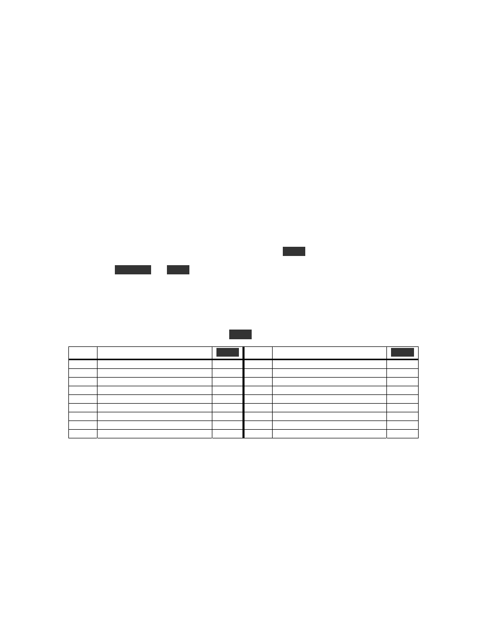
ATU Modes
The table below lists all ATU modes, and what is displayed when
T U N E
is pressed in each mode. AUTO
mode is used most of the time, and occasionally ALT or POUT. (With K2 firmware rev. 1.05 or later,
you can hold
D I S P L AY
and
T U N E
together to force POUT mode.) The other modes are primarily used
for calibration and troubleshooting. If you see LO P in any mode that displays SWR, power is too low to
obtain a stable SWR reading. You should increase the POWER setting if this occurs.
When you switch between CALS mode and AUTO mode, you may hear a few relays switching, since in
C A L S
mode (as well as CALP and CALN) the L and C relays are all reset (L and C are zero). You'll
also hear relays switching if you select the L0-L8, C0-C8, N1, or N2 modes (see Troubleshooting).
In AUTO and ALT modes the ATU terminates
T U N E
automatically.
Mode Description
T U N E
Mode Description
T U N E
CALn Used for C55 calibration; L/C = 0 mVDC
NETx
1=Cin,
2=Cout (present band/ant.)
SWR
CALP Used for calibration of R1; L/C = 0
Power
Txxx
L-C-net combinations tried
SWR
CALS SWR bridge only; L/C = 0
SWR
Exxx
0-199 = error (see Troubleshooting)
SWR
AUTO Normal auto-tune mode
SWR
INIT
Turning power off/on resets all data
SWR
ALT Alternate
auto-tune
mode
SWR Fx.xx KAT2 firmware revision, e.g. F1.00
SWR
POUT Forward/Reverse power display
Power
L0-L8 Individual inductor selection
SWR
x.x-1
SWR from most recent tune-up
SWR
C0-C8 Individual capacitor selection
SWR
Lxx.x
Inductance, µH (present band/ant.)
SWR
N1
Selects Cin network (L/C = 0)
SWR
Cx.xx Capacitance,
nF
(present band/ant.)
SWR
N2
Selects Cout network (L/C = 0)
SWR