24 circuit details, kat2 control board, Control board schematic – Elecraft KAT2 User Manual
Page 24
24
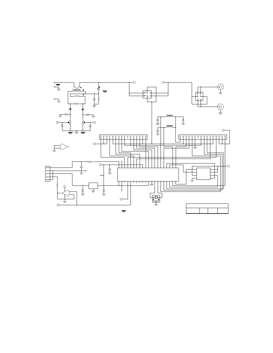
Circuit Details, KAT2 Control Board
T1, D1, D2 (etc.) form a directional coupler for SWR and power measurements. This type of bridge is much more
accurate than the K2's standard RF detector (D9) in the presence of non-50-ohm loads. The bridge output is buffered by
op-amp U4 and routed to the K2 control board, overriding the signal from D9. The bridge outputs are also connected to
A-to-D inputs on the microcontroller, U1. U1 measures these voltages and converts them to SWR or power readings,
using averaging and linearization techniques to improve accuracy. The EEPROM (U2) stores network and SWR data
for each band and antenna. K17 selects either a capacitor-in or capacitor-out network configuration, while K18 controls
the antenna switch. U1 "sleeps" at all times except during actually antenna tune-up, so it generates no receiver noise.
Control Board Schematic
= On bottom of PC board.
C TX/ANT Select
Antenna Switch
W. Burdick
SWR Bridge
CAP COMMON
E. Swartz
Antenna 1
Antenna 2
L-NET OUT
L-NET OUT
Elecraft
L-NET IN
L-NET IN
GND POST
LM78L06
25LC320
5-30pF
4.0MHz
RELAY
COMMON
Rev. Sht.
1N5711
1N5711
16C77
/HOLD
Date
REFL
.001
3.3K
MC
L
R
OS
C
1
OS
C
2
REFL
.001
.001
.001
C55
C54
C50
C51
100
.001
.001
C52
C53
200
K18
FWD
0.1
OUT
C58
0.1
C59
C57
.001
.001
100K
K17
K18
GND
K17
MCU
470
RA4
RC0
RC1
RA0
RA1
RA2
RA3
RA5
RE0
RE1
RE2
VDD
VSS
RC2
RC3
RD0
RD1
RD2
RD3
RC4
RC5
RD4
RD5
RD6
RD7
VSS
VDD
RB0
RB1
RB2
RB3
RB4
RB5
RB6
RB7
RC6
RC7
FWD
/CS
/WP
VSS
SCK
VCC
SDO
SDI
C45
C46
C47
.001
C60
R3
D1
D2
By
J1
J2
R4
R2
R1
10
11
12
13
14
15
16
J4
10
11
12
13
14
15
16
J5
U3
IN
Z1
10
10
RF
R5
10
15
20
21
25
30
35
40
U1
U2
6V
T1
E1
2
4
3
9
7
8
1
2
3
4
5
6
7
8
9
1
2
3
4
5
6
7
8
9
11
2
4
3
9
7
8
1
5
1
2
3
4
5
6
7
8
4
2
3
1
6
5
nc
nc
2 of 2
KAT2 ATU Control Board
54
3
2
1
J3
Aux I/O
(Sheet 1)
AUXBUS
12V
3
2
1
+
-
8
4
U4A
6V
LM358
6V
G
6V
A
B
5
6
7
+
-
U4B
NOT USED
47
R6
F
11/27/00