Figure 4-3 – Cabletron Systems Smart 04-0053-01 User Manual
Page 66
4-10 SmartSwitch ATM User Guide
IP Routing for Management
Routing
To see the route, enter the
show route
command on SW2
SmartSwitch # show route
ROUTE NET TABLE
destination gateway flags Refcnt Use Interface
------------------------------------------------------------------------
0.0.0.0 0.0.0.0 1 0 0 zn0
90.1.1.0 90.1.1.33 1 0 1688 zn1
128.205.99.0 90.1.1.254 1 3 5660 ei0
------------------------------------------------------------------------
ROUTE HOST TABLE
destination gateway flags Refcnt Use Interface
------------------------------------------------------------------------
127.0.0.1 127.0.0.1 5 0 0 lo0
------------------------------------------------------------------------
SmartSwitch #
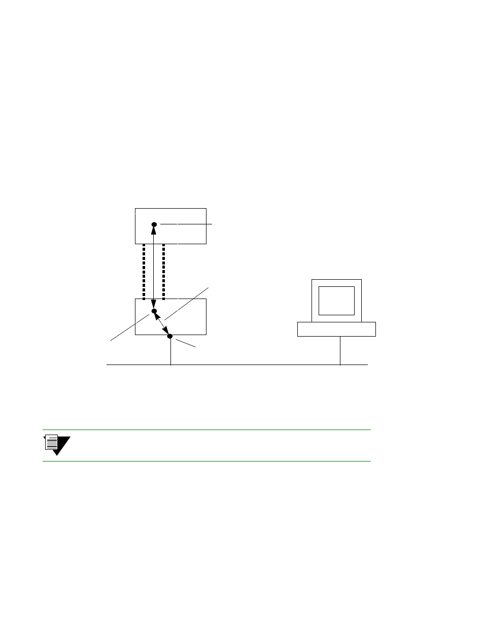
Figure 4-3 IP routing through SW1 for connectivity to the Ethernet network
Note
The NMS must also contain a route that specifies the Ethernet interface of the
Ethernet connected switch as the gateway to the ELAN subnet.
NMS
Ethernet network 128.205.99.0
SW1
SW2
AT
M
L
in
k
ELAN
Switch client
on SW2, 90.1.1.33
Switch client
on SW1,
IP Rou
te
Ethernet interface
90.1.1.254
128.205.99.254
Switch client on SW1 is
defined as SW2’s
gateway to the Ethernet