Iisp routing example one, Iisp routing example two, Figure 4-1 – Cabletron Systems Smart 04-0053-01 User Manual
Page 59: Iisp route across pnni domain -3
SmartSwitch ATM User Guide 4-3
Routing
IISP Routes
IISP Routing Example One
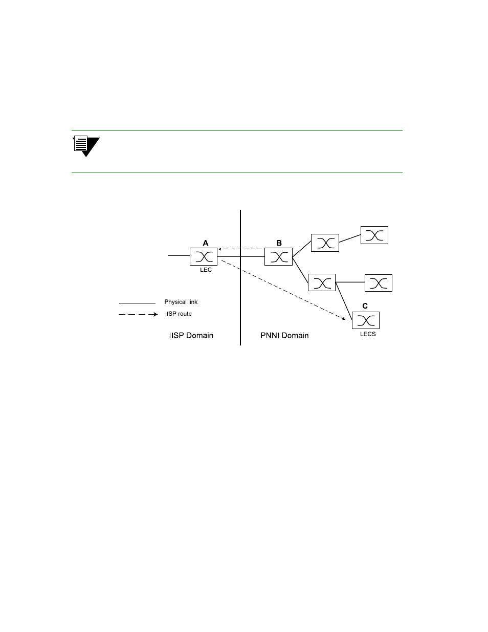
In Figure 4-1 Switch A is an IISP device connected to the PNNI domain through Switch B. Switch A contains an LEC,
which is a member of an ELAN whose LECS is on Switch C (within the PNNI domain). If the LEC on Switch A is to
make contact with the LECS on Switch C, Switch A must contain an IISP route directly to switch C. Furthermore,
Switch B must contain a route to switch A over the physical link that connects the two switches.
Note
Dotted lines in the diagrams below represent one-way IISP routes to the devices
pointed to by the arrowheads. Each route is defined on the device from which the
dotted line originates.
Figure 4-1 IISP route across PNNI domain
IISP Routing Example Two
A second IISP device (Switch D) is added behind Switch A. If Switch D also needs to reach Switch C for LANE
support, additional IISP routes must be defined between Switches D and C, B and D, and A and D. Figure 4-2 shows
the typical “route to every point reached” IISP topology.