Connecting the sensor and relay device, 3 connecting the sensor and relay device – AVer MXR6008 User Manual
Page 12
6
1.4.3 Connecting the Sensor and Relay device
The Sensor, Alarm, and audio port enable you to connect 4 sensor inputs, and 1 relay outputs.
Just connect the external sensor, relay, and audio in/out device pin directly to the pinhole.
Check the table below and locate which pinhole is assigned to sensor input, relay output, and
audio in/out.
The signal from the sensor (i.e., infrared sensors, smoke detectors, proximity sensors, door
sensors, etc.) is being transmitted to the unit and this triggers the system to respond and send
signal to relay device (i.e., alarm, telephone etc).
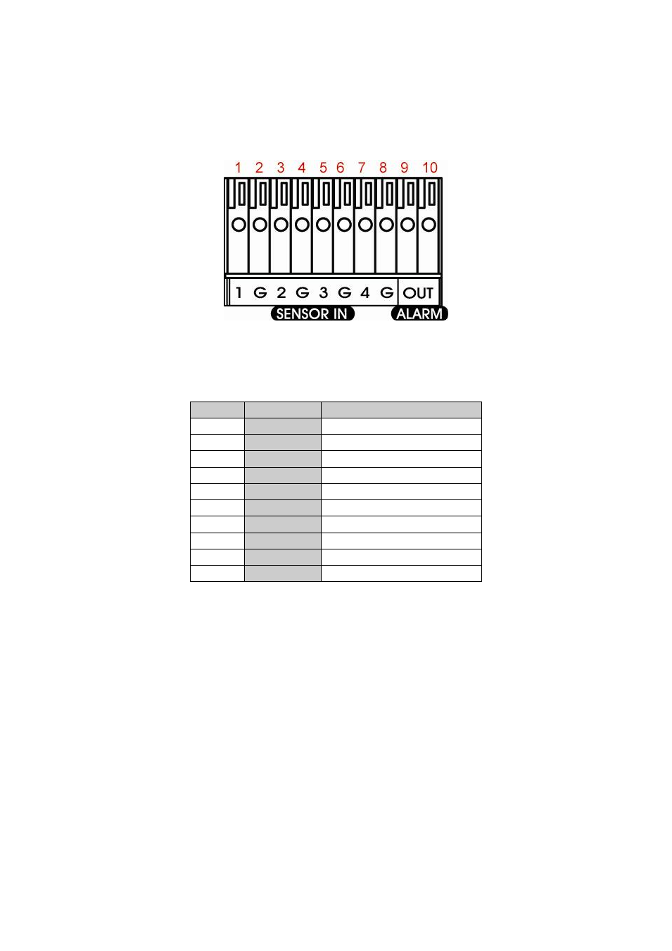
Sensor and Alarm pinhole:
Number
Pin
Definition
1
1
Sensor 1 signal
2
G
Sensor 1 Ground signal
3
2
Sensor 2 signal
4
G
Sensor 2 Ground signal
5
3
Sensor 3 signal
6
G
Sensor 3 Ground signal
7
4
Sensor 4 signal
8
G
Sensor 4 Ground signal
9
Alarm OUT Relay signal
10
Alarm OUT Relay signal