3 back panel, Back panel – AVer MOB1304 User Manual
Page 9
3
1.3
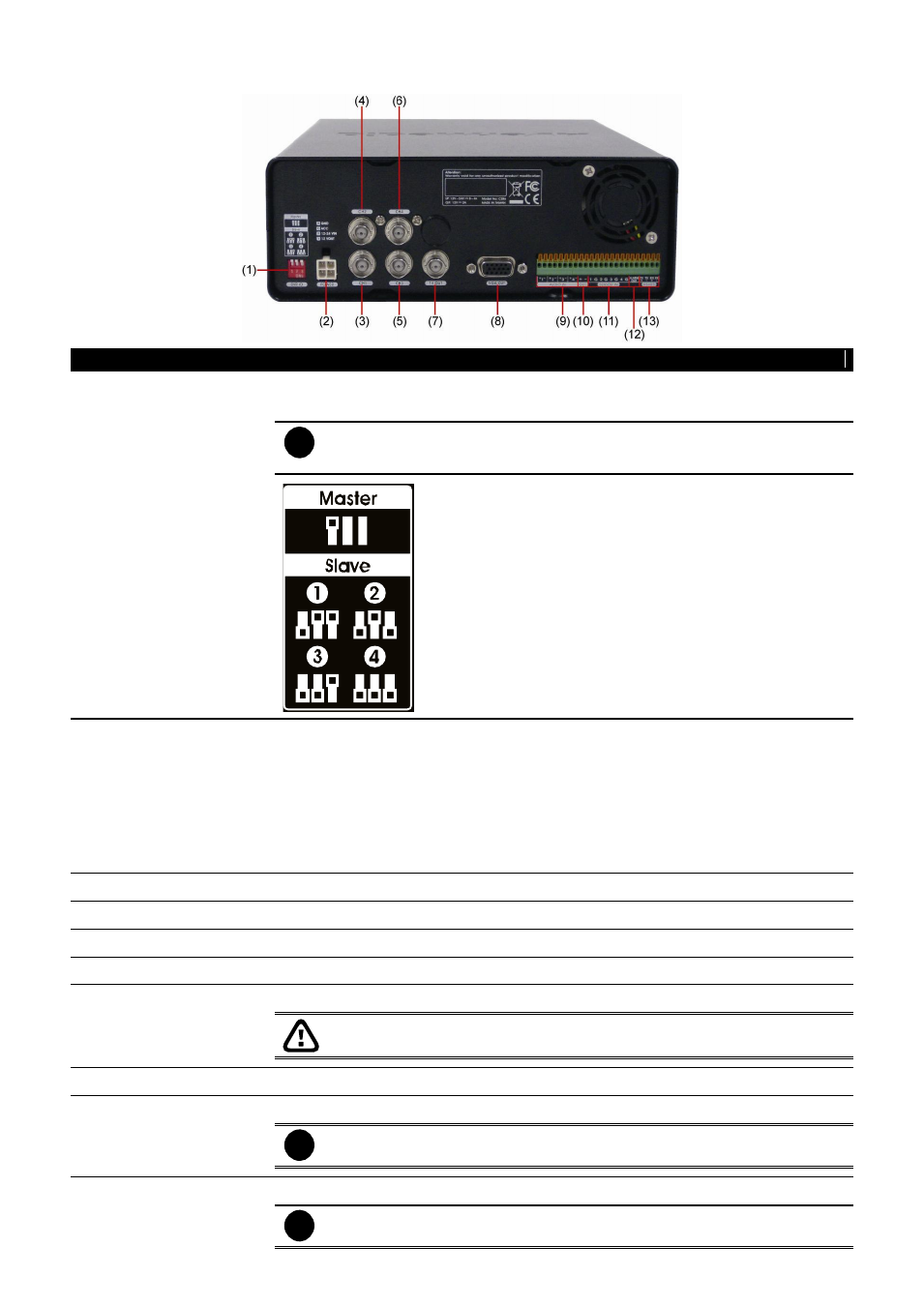
Back Panel
Name
Function
(1) DVR ID switch
To setup an ID identification of DVR for series connection.
Please refer the switch setup direction on rear panel of DVR to setup.
i
- The black spot indicates the position of switch.
- Only one DVR can be the MASTER.
(2) Power plug
Connecting the power cord. The power cord divide into 4 lines and each line has
sticker on it for function description.
GND (Black): Power negative(-) connection and camera negative(-)
connection
12V~24V(Red): Power positive(+) connection
ACC(Green): Connect with the ACC line of vehicle
12V Out(Yellow): Camera positive(+) connection
(3) CH1
Input the video camera signal and display it on channel 1
(4) CH2
Input the video camera signal and display it on channel 2
(5) CH3
Input the video camera signal and display it on channel 3
(6) CH4
Input the video camera signal and display it on channel 4
(7) Video Out (BNC)
Output the video signal to a TV(Call Monitor)
The DVR unit supports dual video output
– Video Out and VGA Out.
(8) VGA Out
Output the video signal to a LCD monitor
(9) Audio In
Input the audio signal from a microphone or audio input device.
i
Microphone with its own power supply is necessary and the internal
amplification must be used.
(10) Audio Out
Output the audio signal to a speaker
i
The audio out device with its own power supply is necessary.