4 connecting the audio/sensor/relay/rs485 device, Connecting the audio/sensor/relay/rs485 device, Audio, sensor, relay and rs485 pinhole allocation – AVer MOB1304 User Manual
Page 17
11
Camera/LCD Monitor Install Location:
LCD Monitor
Camera
i
-
The LCD monitor power can connect to the ignition of bus.
-
The camera power is connected to the DVR camera power cable and plugs the video
cable into DVR video input.
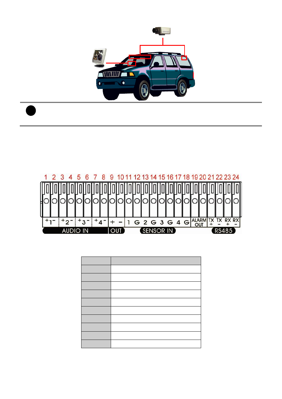
1.4.4 Connecting the Audio/Sensor/Relay/RS485 Device
The Sensor and Alarm ports enable you to connect 4 audio input devices, 1 audio output device,
4 sensor inputs and 1 relay outputs. Just connect the external sensor and relay pin directly to the
pinhole. The RS485 ports allows user to connect the PTZ camera to the DVR unit. Check the
table below and locate which pinhole is assigned to sensor input, relay output, or RS485.
1.4.4.1 Audio, Sensor, Relay and RS485 pinhole allocation
Audio in and out pinhole:
Pin #
Definition
1
Audio 1 input signal +
2
Audio 1 input signal -
3
Audio 2 input signal +
4
Audio 2 input signal -
5
Audio 3 input signal +
6
Audio 3 input signal -
7
Audio 4 input signal +
8
Audio 4 input signal -
9
Audio output signal +
10
Audio output signal -