Reset distribution – Achronix Speedster22i Clock and Reset Networks User Manual
Page 26
26
UG027, May 21, 2014
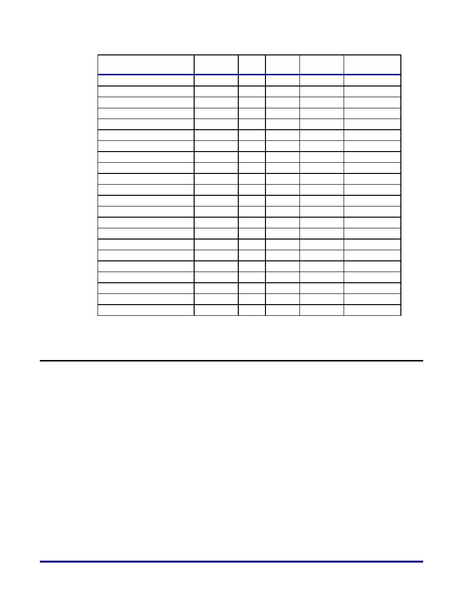
Port_Name
DIFF-PAIR
USE
BANK
PURPOSE
CLK/RST USE
pad0_clk_bank_se
P
C
CB2
USER
CLK RST
pad0_clk_bank_sw
P
C
CB1
USER
CLK RST
pad1_clk_bank_ne
N
C
CB3
USER
CLK RST
pad1_clk_bank_nw
N
C
CB0
USER
CLK RST
pad1_clk_bank_se
N
C
CB2
USER
CLK RST
pad1_clk_bank_sw
N
C
CB1
USER
CLK RST
pad2_clk_bank_ne
P
C
CB3
USER
CLK RST
pad2_clk_bank_nw
P
C
CB0
USER
CLK RST
pad2_clk_bank_se
P
C
CB2
USER
CLK RST
pad2_clk_bank_sw
P
C
CB1
USER
CLK RST
pad3_clk_bank_ne
N
C
CB3
USER
CLK RST
pad3_clk_bank_nw
N
C
CB0
USER
CLK RST
pad3_clk_bank_se
N
C
CB2
USER
CLK RST
pad3_clk_bank_sw
N
C
CB1
USER
CLK RST
pad4_clk_bank_ne
P
C
CB3
USER
CLK RST
pad4_clk_bank_nw
P
C
CB0
USER
CLK RST
pad4_clk_bank_se
P
C
CB2
USER
CLK RST
pad4_clk_bank_sw
P
C
CB1
USER
CLK RST
pad5_clk_bank_ne
N
C
CB3
USER
CLK RST
pad5_clk_bank_nw
N
C
CB0
USER
CLK RST
pad5_clk_bank_se
N
C
CB2
USER
CLK RST
pad5_clk_bank_sw
N
C
CB1
USER
CLK RST
Reset Distribution
Reset signals need to be distributed to both the FPGA core fabric as well as the IO ring, which
includes the GPIOs, SerDes and hard IP. There is no dedicated reset network in the FPGA
programmable fabric, so distribution to the core is generally recommended to be done using
the global and direct clock network resources described above, to take advantage of timing
and load balancing.
For the IO ring, there is a dedicated 16-bit reset bus that ensures a balanced reset assertion
and de-assertion latency across the entire device. This is made possible by pipelining the
reset distribution using the clock to which the reset is synchronized.
Each side of the device has two groups of reset signals running in opposite directions. Each
group consists of eight reset signals each, spanning the entire edge of the device in a
pipelined manner. The two groups of reset signals are tapped at each I/O bank or logic block
(eg. DDR controller, SERDES), using a configurable pipeline multiplexer with configurable
pipelined latency. The configuration is automatically set for each individual multiplexer to
balance the latency for the reset signals across the entire device. The outputs of the pipeline
multiplexer are subsequently distributed to the reset network inside the IO banks and logic
blocks. This is shown in Figure 16 below.