Crmu, Clk div & gating – Achronix Speedster22i Clock and Reset Networks User Manual
Page 18
18
UG027, May 21, 2014
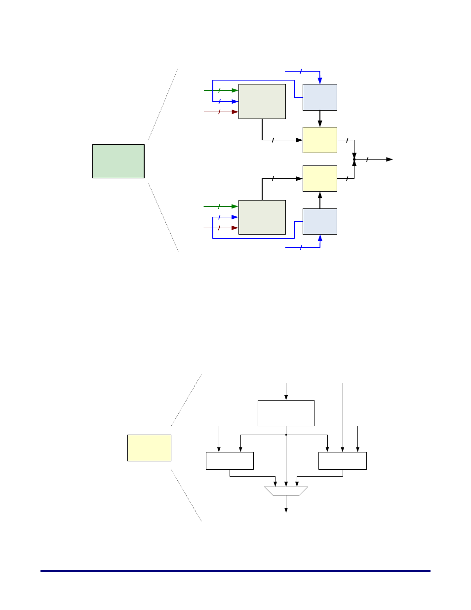
CRMU
32 to 8
Crossbar
Additional
Control
Logic
32 to 8
Crossbar
Additional
Control
Logic
Clk Div &
Gating
Clk Div &
Gating
6
24
2
6
24
Global Core Clocks
from Clock Hub
Direct Core Clocks
from Clock Mux
2
From data
interconnect in fabric
16
From data
interconnect in fabric
16
8
8
8
8
16
To Fabric
Columns
Global Core Clocks
from Clock Hub
Direct Core Clocks
from Clock Mux
Figure 9: Detailed View of a Clock Region Management Unit (CRMU)
Figure 10 below provides a more in-depth look at the 3 features available in the CRMU.
Clock division logic is controlled by static configuration memory bits. The clock gate relies on
an “Enable” input to the logic, while the glitchless clock switch module uses select/deselect
logic to select between 2 different clock inputs. The divider and gating or switching logic can
also be cascaded as shown. Note that Figure 10 is a conceptual view of the circuitry for one
instance only and these functions exist for all of the clock inputs.
Clk Div &
Gating
Clock Divider
(1, 2, 4, 6 or 8)
Clock Gate
Clock Switch
Enable
Select /
Deselect
Clk_Out
Clk_In
Clk_In2
Figure 10: Internals of the Clock Division, Gating and Switching Circuitry