Achronix Speedster22i Clock and Reset Networks User Manual
Page 13
UG027, May 21, 2014
13
The PLL IP comes with a built-in LDO and a Band Gap reference circuit. The LDO takes
external analog voltage (PA_VDD, 1.5V to 1.8V) and generates internal analog voltage to
provide cleaner supply voltage to PLL. The Band Gap reference circuit provides the reference
voltage for the LDO. In order to calibrate the Band Gap reference and the LDO, without
requiring an analog pin, a built-in ADC reference is included in the PLL block as well.
The PLL can be controlled in two ways: one way is to use the direct control through the
interface pins; the other is to use AHB CSR interface. More extensive descriptions of these
controls can be found in UG021 - Speedster22i Macro Cell Library. The PLL performance
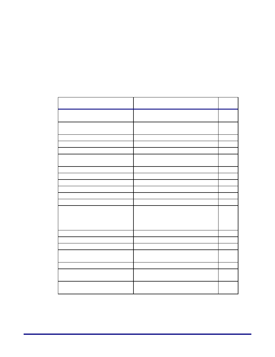
specifications are listed in Table 4 below.
Table 4: PLL Performance Specifications
Performance Features
Units
Bandwidth
Tracking between 1/10th and 1/8th of
reference clk freq
Feedback Divider
8 (2 to 255); in fractional mode, only
support 8 to 254
Bits
Post Divider
6
Bits
Reference Clock Divider
6
Bits
Number of Post Dividers
4
Fractional Synthesizer Support
PLL includes a 16-bit accurate fractional
synthesizer.
Spread Spectrum
No support
Feedback signal delay(max)
Half of divided reference clock period
ns
Operation Mode
Normal, Bypass, Pwrdn, Reset
Internal phase separation
12.5% output cycle
Internal phase accuracy
+/-3.5% output cycle at 2GHz
Output phase accuracy
+/-5% output cycle at 2GHz
Number of selectable Phases
8
Each PLL output clock can select and
change to one of the 8 phases
dynamically in a glitch-free manner.
Maximum Duty cycle variation
50% +/- 2%
Static Phase Error
+/- 80
ps
Jitter – Period
+/- 4% p2p of output clock period
%
Jitter – Cycle to Cycle
5ps (integer divider mode, typical); 8ps
(fractional divider mode, typical)
ps
Jitter – Long Term
Worst case 100ps/sigma
ps
Lock Time
500 ref clk periods (integer mode);
1000 ref clk periods (fractional mode)
Reset divide-by-1 output
frequency range
30MHz – 50 MHz
In ACE, users are provided with the option to configure PLLs using the “Basic PLL” IP
generator or the “Advanced PLL” IP generator. The “Basic PLL” generator helps the users in
setting up and configuring the PLL parameters and modes of operation based on the users
desired behavior.