Clock region, 80 to 48 crossbar, H-tree – Achronix Speedster22i Clock and Reset Networks User Manual
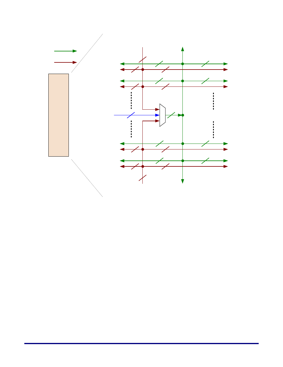
Page 16: Figure 7: detailed view of the clock hub
16
UG027, May 21, 2014
Clock
Hub
32
From Clock Mux Top
32
From Clock Mux Bottom
16
From data
interconnect
in fabric
80 to 48
Crossbar
48
48
48
48
48
48
48
48
48
12
12
12
12
To Clock
Region W1
To Clock
Region W2
12
12
12
12
To Clock
Region Wn-1
To Clock
Region Wn
To Clock
Region E1
To Clock
Region E2
To Clock
Region En-1
To Clock
Region En
Global Core Clk
Direct Core Clk
H-Tree
Figure 7: Detailed View of the Clock Hub
Clock Region
Clock regions in Speedster 22iHD FPGAs have fixed heights, such that a DDR controller on
the left and right sides of the IO ring can feed 3 clock regions each. The width, and
consequently, number of IP columns is variable. This means that both the size and number of
clock regions will vary from one member of the Speedster 22iHD FPGA family to the other.
The total clock region count in any device is 3 x the total number of DDR controllers on the
die. There are an equal number of clock regions on the left and right halves of the device.
Each clock region is fed 48 global and 12 direct clock inputs from the clock hub. The clock
selection for these is detailed in Figure 7 above. In addition a 16-bit bus from the data
interconnect can also be fed here to drive only the clocks in a specific region.
All of these inputs are fed into a Clock Region Management Unit (CRMU) which performs an
appropriate clock selection and outputs a 16-bit bus which is then fanned out to all of the
columns of RLBs, MULTs, LRAMs and BRAMs in that clock region. An illustration of a clock
region is shown in Figure 8 below.