Qmark CWH3000 Series - Commercial Fan-Forced Wall Heaters User Manual
Page 3
NOTE: Wiring Compartment Volume - 119 in3 (1950 cm3).
a. Run a power supply cable into the area above the top of
the wall opening. All wiring must be in accordance with
National and Local electrical codes. Refer to Table 1,
page 1 for correct wire size.
b. Remove disconnect switch bracket by loosening the two
screws on the right side.
c. Install a cable clamp in the knockout in the top of wall back
box.
d. Insert power supply cable through cable clamp, allowing
approximately 6" (152 mm) of cable length to remain
inside the back box to facilitate connections.
3. Mounting Back Box
a. Place the back box into wall opening flush with finished
wall surface on bottom and sides of box. (Top flange of
backbox should protrude approximately 1/2" or 12.7 mm
from finished wall surface).
b. Secure the back box in place with wood screws or nails.
4. Wiring Disconnect Switch
a. Connect the power supply wires to the blue wires of the
disconnect switch using wire connectors (see Wiring
Diagrams, page 5)
b. Ground the back box connecting the supply ground lead
wire to the green ground screw located in the inside top of
the back box.
c. Secure disconnect switch bracket in place by tightening
screws.
Installation of Back Box With Surface Mounting Frame
See Figure 3
1. Secure back box to wall with knockouts in upper right hand
corner using screws and anchors.
2. Hang the surface-mounting frame on the back box. Ensure
that the back edge of the surface-mounting frame is flush
against the wall.
NOTE: If heater is located in a high traffic area where it may be
subjected to vandalism or abuse, take extreme care to see that
the box is firmly attached to the wall.
3. Power Supply Wiring
NOTE: Wiring Compartment Volume - 119 in
3
(1950 cm
3
).
a. Run a power supply cable into the area of the upper right
corner of the mounting frame. Arrangement of wiring to
this point must be in accordance with National and Local
codes. Refer to Table 1 page 1 for proper wire size.
NOTE: If the wiring is to run through the wall, cut a hole in the
area of the top of the wall box. Run the supply wire through this
hole. Then remove the “knockout” from the top of the box and
proceed to step C.
b. Remove the knockout on the top side of the frame.
c. Remove disconnect switch bracket by loosening the two
screws on the right side.
d. Feed the power supply cable through the frame allowing 6"
(152 mm) of lead to remain inside the back box.
e. Secure the power supply cable to the back box (using
cable clamp, connector, or other suitable strain relief)
allowing 6" (152 mm) of lead to remain inside the back
box.
f. Connect supply wires to blue wires of disconnect switch
using wiring connectors (see Wiring Diagrams, page 5).
g. Ground the back box by connecting the supply ground
leadwire to the green ground screw located in the inside
top of the back box.
h. Secure disconnect switch bracket in place.
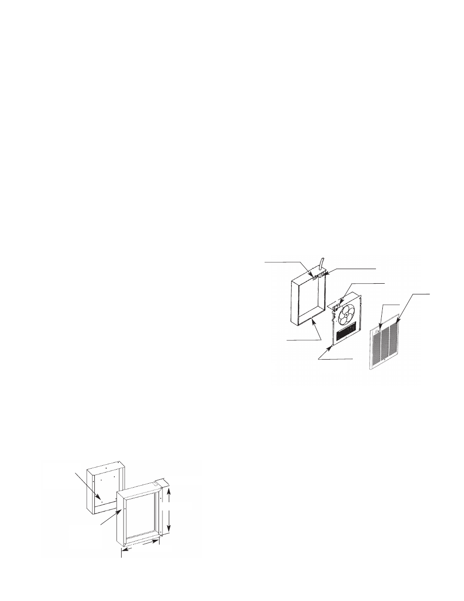
Installation of Heater Assembly and Grille
After back box is completely installed and no further construction
dirt is expected, clean debris from back box, remove heater
assembly from its carton, then refer to Figure 4 and proceed as
follows:
1. Insert the heater assembly into back box, placing the four
mounting holes (with key-hole slots) over the screws in the
back box. Tighten all screws securely.
2. If surface-mounting frame is used, ensure that the frame is
even with all four heater assembly tabs before tightening
screws.
3. Connect the two ON/OFF switch wires to the heater control
switch (thermostat) leads using wire nuts. After connection,
push wires back into the opening.
4. Turn thermostat to the extreme counterclockwise position.
5. Push ON/OFF switch into ON position.
6. Mount the grille tabs over back box flange (top).
7. Insert screw through bottom hole on grille. The screw threads
into the hole on fan panel. Tighten screw until grille is flush to
wall (or surface mount frame).
Be careful, do not
overtighten.
8. Push thermostat knob onto thermostat shaft.
3
3-13/16" (97mm)
HANG FRAME
ON BACK
BOX
MOUNT BACK
BOX TO WAll
USING REAR
MOUNTING
HOlES
19" (482mm)
15-5/32" (385mm)
Fig. 3: Surface Mounting Installation
Fig. 4
POWER lEADS
THERMOSTAT
KNOB
GRIllE
DISCONNECT
SWITCH
BACK BOX
HEATER
ASSEMBlY