Installation instructions – Qmark CWH3000 Series - Commercial Fan-Forced Wall Heaters User Manual
Page 2
2
INSTAllATION
INSTRUCTIONS
NOTE: This heater has a continuous fan-only feature. See
page 4,
Operation Instructions, step #4 for details.
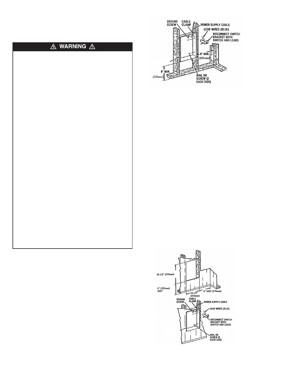
Installation of Back Box in New Construction
1. Mounting Back Box (See Figure 1).
a. Place the back box between two 16" (406 mm) center-
to-center wall studs at the desired mounting height but
no closer than 8" (203 mm) to adjacent wall or floor.
NOTE: If wall studs are spaced greater than 16” on center,
additional framing supports may be necessary.
b. Align back box such that the bottom and sides will be
flush with finished wall surface (top flange of back box
should protrude approximately 1/2" (12.7 mm) from
finished wall surface).
c. Secure the back box in position with wood screws or
nails as shown in Figure 1.
Not for ceiling mount.
2. Power Supply Wiring (See Figure 1)
NOTE: Wire compartment volume - 119 in
3
(1950 cm
3
).
a. Run a power supply cable into the knockout area in the
upper right hand corner of the back box. All wiring must be
in accordance with National and Local Electrical Codes.
Refer to Table 1, page 1 for correct wire size.
b. Remove disconnect switch bracket by loosening two
screws on the right side.
c. Install a cable clamp in the knockout in the top of the back
box.
d. Insert power supply cable through cable clamp, allowing at
least 6" (152 mm) of leads to extend inside the back box.
Connect the blue lead wires of disconnect switch to the
supply wire leads using wire connectors (see Wiring
Diagrams, page 5).
e. Ground the back box by connecting the supply ground
lead wire to the green ground screw located in the inside
top of the back box.
f. Secure disconnect switch bracket in place by tightening
screws.
Installation of Back Box in Existing Construction
1. Provide a wall opening 14-1/2" (362 mm) wide by 18-1/2"
(470 mm) high at the desired mounting height, but no closer
than 8" (203 mm) to adjacent wall or floor. (See Figure 2.)
NOTE: Locate so at least one side of opening is at wall stud.
2. Power Supply Wiring
To prevent a possible fire, injury to persons or damage to the
heater, adhere to the following:
1. Disconnect all power coming to heater at main service
panel before wiring or servicing.
2. All wiring procedures and connections must be in
accordance with the National and Local Codes having
jurisdiction and the heater must be grounded.
3. Power supply must enter back box through the knockouts in
the RIGHT side of box(see Figure 1). See also TOP
marking on the back box for proper orientation.
4. Verify the power supply voltage coming to heater matches
the ratings as shown on the heater nameplate.
CAUTION: ENERGIzING HEATER AT A VOLTAGE GREATER
THAN THE VOLTAGE PRINTED ON THE NAMEPLATE
WILL DAMAGE THE HEATER AND VOID THE WARRANTY
AND COULD CAUSE A FIRE.
5.
CAUTION - High temperature, risk of fire, keep electrical
cords, drapery, furnishings, and other combustibles at least
3 feet (0.9 m) from front of heater. Do not install heater
behind doors, below towel racks, in the ceiling or in an area
where it is subject to being blocked by furniture, curtains or
storage materials. Hot air from the heater may damage
certain fabrics and plastics.
6. To reduce the risk of fire, do not store or use gasoline or
other flammable vapors and liquids in the vicinity of the
heater.
7. This heater is to be mounted only using back box and may
be installed with the back box recessed or surface mounted
as described within this manual.
8. The following minimum clearances must be maintained:
Bottom of heater to floor - 8” (203 mm).
Sides of heater to adjacent wall - 8” (203 mm).
Top of heater to ceiling - 36” (915 mm).
9. Do not operate the heater without the grille installed.
10. Do not use this heater for dry out as the paint, plaster,
sawdust and drywall sanding dust will permanently damage
the heater and must be kept out of the heater.
Fig. 1: Locating Recessed Back Box in New Construction
BACK BOX
Fig. 2: Locating Recessed Back Box in Existing Construction
BACK BOX