Operating instructions – Qmark CBD Series - Heavy-Duty Commercial Baseboard Heaters User Manual
Page 4
Installation of Multiple Units
1. With heaters mounted end-to-end, allow 1/32-inch (1mm) of
expansion space per heater between each heater.
2. For each heater to be installed, refer to and follow
“Installation of Single Unit”, Steps 1 through 7.
3. If the power supply is to enter through the end of the heater
series so that the end cap can be installed after the heaters
are installed, continue “Installation of Single Unit”, Steps 8
through 11.
4. If the power supply is to feed heaters at the junction box that
is adjacent to another heater, it is easier for the power supply
connections to be made prior to the installation of the
heater(s) to the wall. If this is not possible, connections may
be made through the opening in the junction boxes when the
front cover(s) is removed. See Figure 8.
5. Connecting power supply cables may be routed from heater
to heater by drilling a 1/2-inch (13mm) diameter hole in the
end caps for the heaters that fit together. See Figure 9.
To prevent possible damage to internal heater wiring, all
drilling of end caps must be done with end caps removed
from heater.
6. Wire heaters as shown in Wiring Diagram, Figure 10.
7. Replace the front covers and end caps according to
“Installation of Single Unit”, Steps 11 and 12.
OPERATING INSTRUCTIONS
1. This heater must be properly installed before it is used.
2. An integral or remote wall thermostat is recommended for
each room. In very large rooms it is recommended that a low
voltage thermostat with double or multiple circuit relays be
used to provide the most comfortable results.
DO LOCATE
DO NOT
THERMOSTAT
LOCATE THERMOSTAT
• A minimum of two feet
• Near televisions or
(61cm) from any
appliances that emit heat.
outside wall.
• Near drafts from an
• Approximately five feet
open doorway.
(1,5m) from the floor,
• Where it would be struck
preferably on an inside
by direct rays of sunlight.
wall location.
3. After the baseboard system has been completely installed,
all thermostats should be turned to LOW or NO HEAT set-
ting. Then turn on breakers or install fuses. Wait 3 to 5 min-
utes and check to see that none of the heaters are operating.
If operating, disconnect power and check wiring. If none are
operating then turn the thermostats to highest setting and
wait 3 to 5 minutes. Check to see that all heaters are operat-
ing. Should any not be operating, disconnect power and
check wiring.
4. Allow entire system to operate steadily for 1/2-hour. For a
period of time after the heaters are put into operation, the
owner may notice a “new smell” coming from the heaters.
This is expected on new installations. Bringing heaters to full
operation will eliminate this condition in a short period of
time.
5. Select the setting for comfort on all thermostats.
6. There are safety over-temperature limiting devices inside this
heater. These safety devices are there to turn off the heater
automatically in the event of an over-temperature condition.
These devices are not to be tampered with or disconnected
from the electrical system. If the heater is installed correctly
and wired to the correct voltage, these devices should never
operate to turn off the heater. If this device is cycling the
heater off and on, turn off power to the heater and have the
heater serviced by qualified service personnel.
4
AFTER CONNECTING POWER
SUPPLY CABLE TUCK WIRING
BACK INTO THE JUNCTION BOX
Figure 8. Wiring Through Junction Box Opening
FRONT OF
HEATER
1
15
/
32
"
(37mm)
1
/
2
" DIA.
(13mm)
3"
(76mm)
Figure 9. End Cap Drill Pattern
LIMIT
ELEMENT
LIMIT
ELEMENT
TWO HEATERS ON ONE SUPPLY
POWER SUPPLY
Figure 10. Dual Heater Wiring Connections
WIRING DIAGRAM
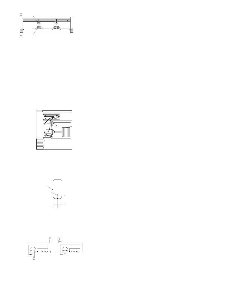
SNAP COVER ONTO TOP OF ELEMENT SUPPORT BRACKET.
SNAP COVER ONTO BOTTOM OF ELEMENT BRACKET.
1
2
Figure 7. Cover Attachment