Qmark CBD Series - Heavy-Duty Commercial Baseboard Heaters User Manual
Page 3
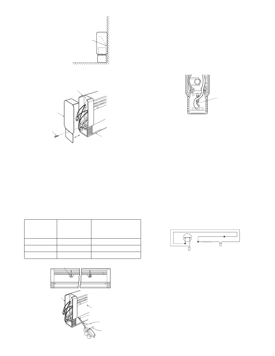
3. Remove the left or right junction box end cap by removing
the screw in the end of the heater and sliding the cap out-
ward from the heater (Figure 3).
4. Remove the front cover of the heater by removing the
screws in the lower corners. Pull the bottom of the cover out-
ward and lift the top of the cover off the junction box. Repeat
for the opposite end. Snap the top of the cover off the center
bracket and off the intermediate supports. See Figure 4.
5. If wires are to enter or pass through raceway, remove race-
way cover and remove the appropriate electrical knockout
from the back of the heater or raceway as necessary.
6. If one or more heaters are connected to a single branch cir-
cuit, determine the total amperage load (see Specifications
Table on page 4), then determine the power supply wire size
and the circuit breaker or fuse size required (See Table 2).
Table 2.
Minimum
Circuit
AWG Wire
Breaker
Total
Size
or Fuse
Amps
(Copper)
Size
0 thru 12
#14
15 Amp
12.1 thru 16
#12
20 Amp
16.1 thru 24
#10
30 Amp
7. Bring power supply wire to the heater and thermostat loca-
tions as determined by the thermostat option selected.
IF POWER SUPPLY IS TO ENTER HEATER THROUGH
KNOCKOUT IN BACK OF HEATER, install wire using cable
clamp leaving 6 to 8-inches (152 to 203mm) of wire inside
heater for connections.
IF POWER SUPPLY ENTERS HEATER THROUGH RACE-
WAY, install wire using cable clamp at the knockout in the
raceway, and feed the wire into the junction box leaving 6 to
8-inches (152 to 203mm) of wire inside junction box for con-
nections. DO NOT make connections in raceway.
NOTE: No clamp is required where the cable passes through
the hole in the plastic junction box.
8. Position the heater on the wall and locate wall studs. Drill or
punch holes through the enclosure back (above the element)
at stud locations.
NOTE: The heater enclosure is provided with nail point marks
showing correct locations for mounting holes.
The following methods of mounting the heaters to common
types of wall surfaces are suggested:
a. Plaster Walls: Use toggle or molly screw anchors.
b. Wall Studs: Use #12 round head screws penetrating at
least 3/4" (19mm) into stud.
c. Masonry Walls: Use #12 round head screws into lead, plas-
tic, or fiber expansion anchor.
Tighten all screws snugly, then back off 1/2-turn to allow the
back panel to expand and contract.
9. Connect supply wiring to heater as described in Figure 6, or
as shown in the wiring diagrams supplied with the accessory
kits intended for use with this heater.
10.Secure the desired accessories to baseboard as shown in
the accessory instruction sheet, and use the wiring diagram
supplied with the accessory.
NOTE: Baseboard heaters must be thermostatically controlled.
11.Replace the front cover by fitting the top lip of the cover onto
the tabs on each junction box and top edge of the element
support bracket(s). Rotate the cover downward, pushing the
bottom corners inward. Install two screws (removed in Step
4) through the cover into the junction boxes. See that the
bottom of the cover is engaged onto the bottom of each ele-
ment support bracket. See Figure 7.
12.Replace the end cap(s) by installing screw(s) (removed in
Step 3).
3
NOTE: ALLOW 1/8" (3mm) MINIMUM
CLEARANCE AT ENDS OF HEATER FOR
EXPANSION AND CONTRACTION
NAIL POINTS
FLOOR
Figure 2. Installation of Heater
JUNCTION
BOX
JUNCTION
BOX END
CAP
SCREW
HEATER
Figure 3. Removal of End Cap
SNAP TOP OF COVER OFF THE CENTER BRACKET/
INTERMEDIATE SUPPORTS
JUNCTION BOX
HEATER COVER
SCREW
Figure 4. Removal of Front Cover
POWER
SUPPLY
CABLE
Figure 5. Routing of Power Supply Cable
LIMIT
ELEMENT
WIRENUT
WIRENUT
CONNECT POWER SUPPLY TO EITHER END OF HEATER BY REMOVING
WIRENUT AND CONNECTING HEATER LEADS INDIVIDUALLY TO SUPPLY
LEADS.
Figure 6. Heater Wiring Connections
WIRING DIAGRAM