Installation instructions – Qmark CBD Series - Heavy-Duty Commercial Baseboard Heaters User Manual
Page 2
INSTALLATION INSTRUCTIONS
Clearances
Floors & Carpeting: Heaters may be mounted directly on any
floor surface, including carpeting. Where wall-to-wall carpets are
installed after the baseboard installation, the carpeting can be
run up to the front and around the heater body.
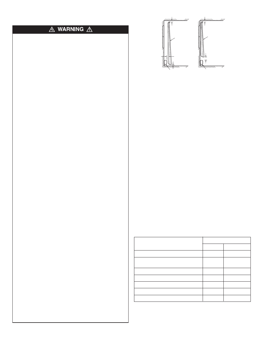
Full Length Drapes The following clearances must be
maintained:
1. Hang drapes so that, in use, they extend below the center
line of the heater, but with at least 1” (25mm) clearance from
the top of the finished floor covering, such as carpet, tile, etc.
2. Hang drapes so there is at least 2” (51mm) between the
extreme front of the heater and the nearest fold of drapes, in
the folded back position (open drape position).
3. Hang drapes so there is at least 1” (25mm) between the top
of the drapes and the ceiling.
Short Drapes: Hang drapes so there is at least 6” (152mm)
clearance above the top of the heater.
Furniture: Do not place furniture against heater. It is recom-
mended all items be kept a minimum of 6” (152mm) inches from
heater.
Installation of Single Unit
Commercial baseboard heaters are designed for installation in
new or existing construction. In existing construction, baseboard
molding should be removed and the heaters mounted flush
against the wall surface. When replacing molding allow 1/16”
(1 mm) clearance between molding and ends of heaters.
NOTE: This heater can be wired in either the right or left hand
junction box. See Table 1 for wiring compartment volumes.
Table 1. Field Wiring Compartment Volumes
Est. Net Total Volume
Description
CM
3
In
3
Heater Wiring Compartment (One End)
200
13.25
Heater Wiring Compartment with
T1 or T2 Thermostat Accessory
175
11.25
Accessory Blank Section (No Controls)
2400
145
AC Accessory Section
2300
140
DR Accessory Section
2300
140
CDS2 Accessory Section
2300
140
LVR Accessory Section
2100
130
1. Position the heater at the desired location on the wall as
shown in Figure 2. For maximum heating comfort, position
the heater under a window.
2. Mark the location on the wall or floor for the power supply
entry into the heater. Remove the heater from the wall and
drill appropriate hole in the wall or floor.
TO REDUCE THE RISK OF FIRE AND ELECTRIC SHOCK
OR INJURY TO PERSONS, OBSERVE THE FOLLOWING:
1. Serious injury or death could result from electric shock.
Make sure electrical power supply circuit coming to heater
is disconnected at main disconnect or service panel before
installing this heater.
2. Wiring procedures and connections must be in accordance
with the National Electrical Code (NEC) and local codes.
Refer to Wiring Diagram Figures 6 and 10 as well as Tables
1 and 2. Make sure all electrical connections are tight to
prevent possible overheating. Use Copper Supply Wire
Only.
3. Verify the electrical power supply voltage matches the volt-
age rating as printed on the heater nameplate.
CAUTION - Never connect a heater to a voltage greater than
the nameplate voltage as this will damage the heater and
could cause a fire.
4. Check to see that all packing pads and materials are
removed from heater before installing.
5. Do not install the heater against combustible low-density
cellulose fiberboard surfaces, against or below vinyl wall
coverings, or below any materials that may be damaged by
heat such as vinyl or plastic blinds, curtains, etc.
6. Do not install heater below an electrical convenience recep-
tacle (outlet).
7. CAUTION – Heater Operates at High Temperatures. Keep
Electrical Cords (including telephone and computer cables),
Drapes, and Other Furnishings Away From Heater. For effi-
cient and safe operation, we recommend maintaining a min-
imum of 6 inches (152 mm) clearance above and in front of
the heater at all times. See Clearances section and Figure
1 for minimum clearance requirements.
8. To reduce the risk of fire, do not store or use gasoline or
other flammable vapors or liquids in the vicinity of the
heater.
9. Do not install heater upside down or in any position other
than as shown in this manual.
10. Do not recess heater in wall or install heater inside any type
enclosure (unless specifically approved by the manufactur-
er) as this will cause heater to overheat and could create a
hazard.
11. When mounting heater, use care when drilling mounting
holes and mounting heater to building structure to avoid
damaging internal heater components. Be sure to loosen
mounting screws ½ turn to allow for expansion and con-
traction.
12. Do not remove or bypass the safety limit control(s) as this
could allow heater to become a fire hazard – see heater
wiring diagrams Figures 6 and 10.
13. All field wiring brought into the heater must be rated at least
90 °C.
14. Do not allow objects to be placed on top of heater as they
may be damaged or create a fire hazard.
15. Heater may be mounted on finished floor or may be mount-
ed above finished floor (such as above baseboard).
However, if installed above floor, power supply must enter
heater through knockout in the back of the heater.
2
2" (51mm) CLEARANCE
(MIN)
1" (25mm) CLEARANCE
(MIN)
BASEBOARD HEATER
EXAMPLE 1
W
A
L
L
FLOOR
CEILING
1" (25mm) CLEARANCE
(MIN)
DRAPERY
6" (152mm) CLEARANCE
(MIN)
BASEBOARD HEATER
EXAMPLE 2
W
A
L
L
FLOOR
CEILING
DRAPERY
1" (25mm) CLEARANCE
(MIN)
Figure 1. Positioning Drapery Near Heater