Line card and route processor overview, Fail (yellow)—the card in that slot is faulty – Cisco XR 12410 User Manual
Page 27
1-13
Cisco XR 12410 and Cisco XR 12810 Router Installation Guide
OL-17441-01
Chapter 1 Product Overview
Line Card and Route Processor Overview
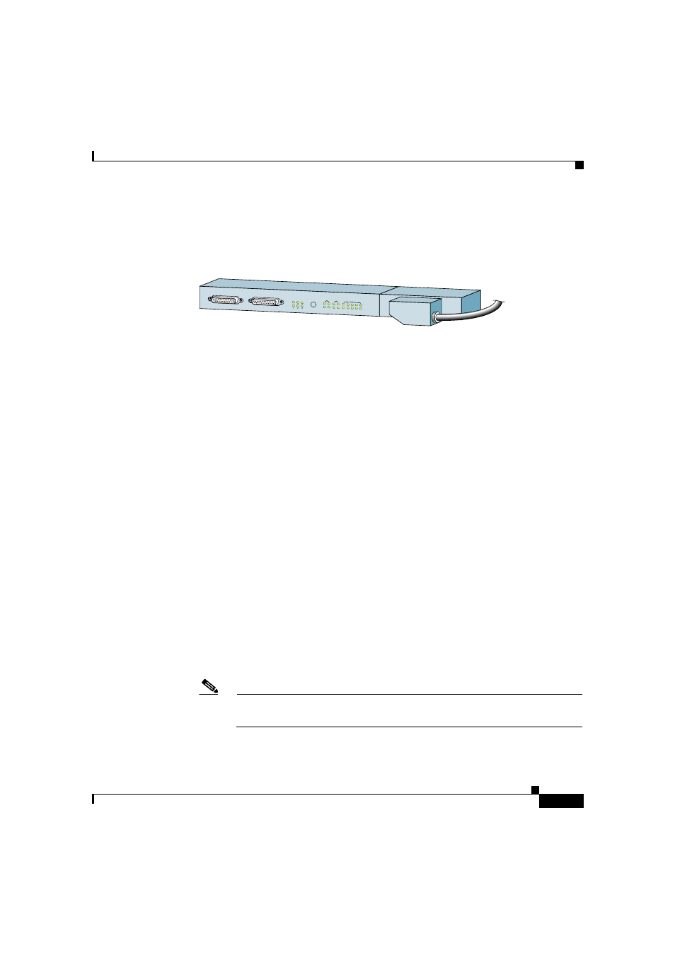
The following connectors and LEDs are on the front panel of the alarm display
(
Figure 1-8
Alarm Display
•
Cable connections for the two alarm cards (labeled Alarm A and Alarm B)
•
Critical, Major, and Minor LEDs that identify system level alarm conditions
•
A pair of status LEDs that correspond to each of the 9 card slots in the switch
fabric and alarm card cage (seven fabric cards and two alarm cards):
–
ENABLED (green)
On—The card installed in that slot is operational and functioning
properly.
Off—Either the slot is empty or the card installed in that slot is faulty.
–
FAIL (yellow)—The card in that slot is faulty.
Line Card and Route Processor Overview
The line card and route processor (RP) card cage has 10 user-configurable slots
that support a combination of line cards and either one or two RPs (see
). Router configurations can consist of either nine line cards and one
RP, or eight line cards and two RPs (one primary and one redundant) using the
following slot configurations:
•
Slots 0 to 7 accommodate the newer (wider) line card designs. These wider
line card slots can also accept narrower legacy line cards.
•
Slots 8 and 9 only accept RPs or a narrower legacy line card.
Note
If a system uses only one RP install it in slot 9. You can use slot 8 for a
legacy line card.
ALARM A
ALARM B
A
A
MBUS
MIN
OR
B
FAIL
ENABLE
MA
JO
R
CR
ITIC
AL
B
0
CSC
1
0
SFC
1
2
3
4
53368