Dell Vostro 1510 (Early 2008) User Manual
Page 47
Processor Module
47
FILE LOCATION: C:\Documents and Settings\sarah_cook\Desktop\Tsing
Ma\SM\A01\EN\Source\cpu.fm
DELL CONFIDENTIAL – PRELIMINARY 9/4/09 - FOR PROOF ONLY
NOTICE:
Ensure that the cam lock is in the fully open position before seating the
processor module. Seating the processor module properly in the ZIF socket does
not require force. A processor module that is not properly seated can result in an
intermittent connection or permanent damage to the microprocessor and ZIF
socket.
NOTE:
If you are installing a new processor, you will receive a new thermal-
cooling assembly which will include an affixed thermal pad, or you will receive a
new thermal pad along with a tech sheet to illustrate proper installation.
This procedure assumes that you have completed the removal procedure
"Removing the Processor Module" on page 45.
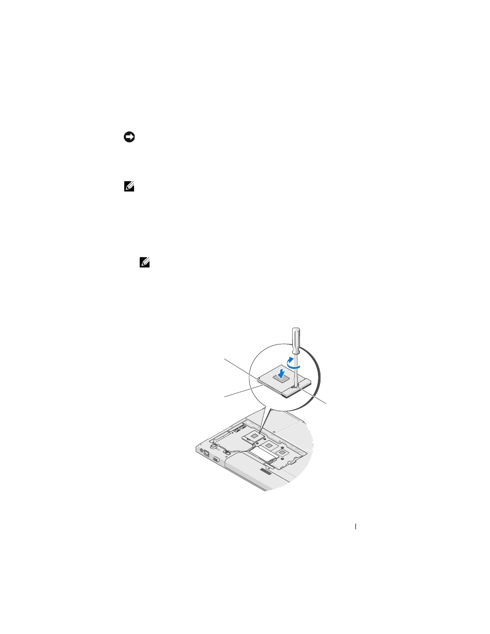
1 Align the pin-1 corner of the processor module with the pin-1 corner of the
ZIF socket, then insert the processor module.
NOTE:
The pin-1 corner of the processor module has a triangle that aligns
with the triangle on the pin-1 corner of the ZIF socket.
When the processor module is properly seated, all four corners are aligned
at the same height. If one or more corners of the module are higher than
the others, the module is not seated properly.
1
2
3