Figure 1-6, Split-bus module – Dell PowerVault 221S (SCSI) User Manual
Page 6
Introduction: Dell PowerVault 220S and 221S Systems Installation and Troubleshooting Guide
file:///C|/Users/rishi_sood/Desktop/220s/en/it/6f704c11.htm[3/7/2013 12:07:17 PM]
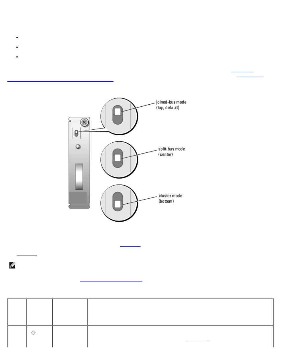
Split-Bus Module
Your storage system supports three SCSI bus modes controlled by the split-bus module:
Joined-bus mode
Split-bus mode
Cluster mode
These modes are controlled by the position of the bus configuration switch when the system is turned on.
illustrates the switch position for each mode. For more information on configuring the SCSI bus modes, see "
System for Joined-Bus, Split-Bus, or Cluster Mode
."
Figure 1-6. Bus Configuration Switch Modes
The only difference between cluster mode and joined-bus mode is the SCSI ID assigned to the enclosure services processor
on the EMM. When cluster mode is detected, the processor SCSI ID changes from 6 to 15. As a result, SCSI ID 15 is disabled,
leaving 13 available hard drives in cluster mode. This allows a second initiator, such as a host bus adapter or RAID controller
card on a second host system, to use SCSI ID 6 (see
for SCSI ID assignments).
for a description of split-bus module modes and functions.
NOTE:
To change the SCSI bus mode, you must change the position of the bus configuration switch before turning on
the storage system. Changing the position of the bus configuration switch while the system is on will not affect system
operation. If you change the configuration, you must first reboot the storage system, and then the host system for the
changes to take effect. See "
."
Table 1-4. Split-Bus Module Modes
Mode
LED Icon Position of
Bus
Configuration
Switch
Function
Joined-
bus
mode
Top
LVD termination on the split-bus module is disabled, electrically joining the two SCSI
buses to form one contiguous bus. In this mode, neither the split-bus nor the cluster
LED indicators on the front of the system (see
for locations) are
illuminated.