Memory modules, Figure 4, Lift the backplane board out of the system (see – Dell PowerEdge 2600 User Manual
Page 48: Replacing the scsi backplane board
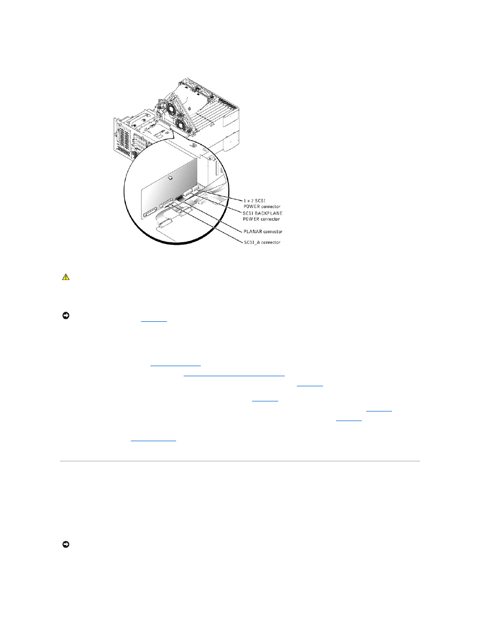
Figure 4-28. Removing and Replacing the SCSI Backplane Board
Replacing the SCSI Backplane Board
1.
Lower the backplane board into the system.
2.
Align the backplane board onto the board's grounding tabs.
3.
Slide the backplane board down about 0.5 inch.
4.
Tighten the thumbscrew on the backplane board.
5.
Install all SCSI hard drives (see "
6.
Install the SCSI backplane daughter card (see "
Installing the SCSI Backplane Daughter Card
").
7.
Insert the SCSI_A cable into the SCSI_A connector on the back of the SCSI backplane board (see
8.
Pull the locking bar to the unlock position to insert the flat cable connector (BKPLN) into the PLANAR CONNECTOR on the back of the SCSI backplane
board; next, push the locking bar to lock the flat cable into the connector (see
9.
Insert the 14-conductor power cable into the SCSI BACKPLANE POWER connector on the back of the SCSI backplane board (see
).
10.
Insert the 4-conductor power cable into the 1 x 2 POWER connector on the back of the SCSI backplane board (see
).
11.
Insert the front fan cable into the P1 connector on the front of the SCSI backplane board.
12.
").
13.
Reconnect your system and peripherals to their electrical outlets, and turn on the system.
Memory Modules
The six memory module connectors on the system board can accommodate a minimum of 256 MB of registered memory modules. The memory module
connectors are arranged in pairs which consist of three banks (bank 1, bank 2, and bank 3).
Memory Upgrade Kits
The system is upgradable by installing combinations of 128-, 256-, 512-MB, or 1-GB registered DDR SDRAM modules. You can purchase memory upgrade kits as
needed.
CAUTION:
Only trained service technicians are authorized to remove the system cover and access any of the components inside the system. See
your System Information Guide for complete information about safety precautions, working inside the computer, and protecting against
electrostatic discharge.
NOTICE:
To avoid damage to the system, align the bottom of the backplane board in the board's mounting grooves before rotating the top of the board
NOTICE:
The memory modules must be PC-2100 compliant.