Expansion cards, Expansion card installation guidelines, Pci bus scan order – Dell PowerEdge 2600 User Manual
Page 36: Installing an expansion card
2.
Guide the cables up and insert them into their connectors on the system board:
a.
Insert the smaller connector into system board connector PDB (see
b.
Insert cable connector P18 into the system board connector GROUND (see
c.
Insert cable connector P17 into the system board connector POWER (see
3.
Install the four screws that secure the PDM to the back panel (see
).
Expansion Cards
The system includes seven expansion slots. The expansion cards are installed on the system board (see
Figure 5
-3
to identify the expansion slots).
Expansion Card Installation Guidelines
You can install expansion cards of different operating speeds on the same bus; however, the bus will operate at the slowest operating speed of the cards on
that bus. For example, if one card on the bus has an operating speed of 66 MHz and the other card has an operating speed of 100 MHz, the bus will only
operate at 66 MHz.
To identify expansion slots, see
Figure 5
-3
.
lists the PCI bus and operating speed for each expansion-card slot.
Table 4-1. Expansion Slot Speeds
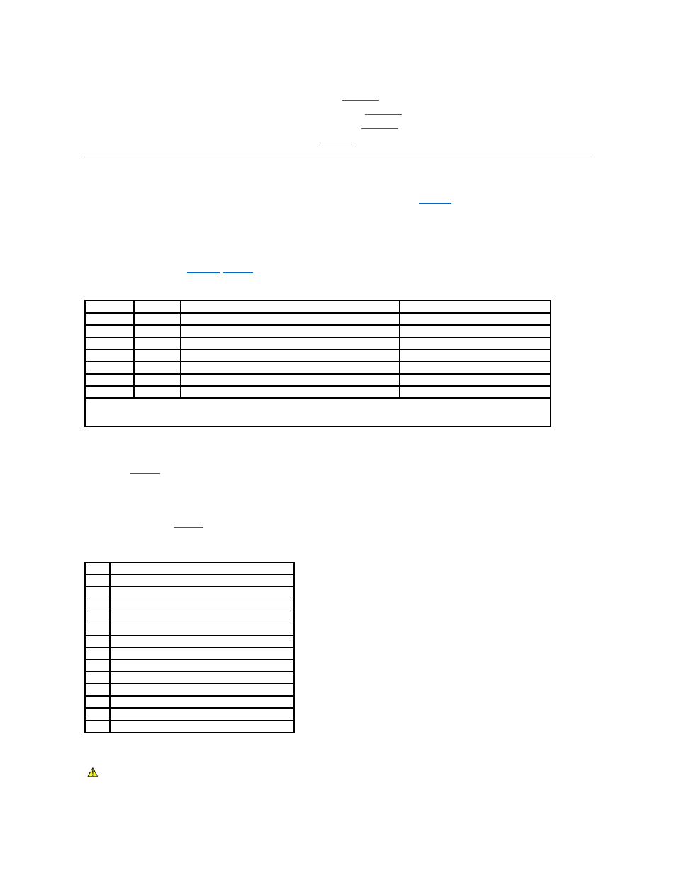
PCI Bus Scan Order
The system's BIOS scans and numbers PCI buses and devices during startup. Expansion slots are scanned according to the host bus ordering, not by the slot
numbers. See
for the order in which the expansion slots and embedded PCI devices are scanned.
An additional factor affects the assignment of PCI bus numbers: an expansion card may have its own PCI bridge chip which requires the assignment of a bus
number for the card as well as one for the bridge. A particular expansion card may have two PCI bridge chips which would result in three sequential PCI bus
numbers all assigned in the same expansion slot.
If you install expansion cards, you may have some difficulty in directly determining the bus number of a controller on a particular expansion card. However, the
PCI bus scan order listed in
can help determine the relative numbering of PCI buses within the expansion slots. For example, a PCI controller
residing in expansion slot 3 will never have a lower bus number than one in slot 2 because slot 2 precedes slot 3 in the scan order.
Table 4-2. PCI Bus Scan Order
Installing an Expansion Card
Slot
Bus
Operating Speed
Signaling Level
1
0
33 MHz
5 V
2
5
33, 66, or 100 MHz
3.3 V
3
5
33, 66, or 100 MHz
3.3 V
4
4
33, 66, or 100 MHz
3.3 V
5
4
33, 66, or 100 MHz
3.3 V
6
3
33, 66, 100, or 133 MHz
3.3 V
7
2
33, 66, 100, or 133 MHz
3.3 V
NOTE:
If you are using expansion cards of different operating speeds, you should install the fastest card in slot 7 and the slowest card in slot 1.
NOTE:
Do not install Dell™ PowerEdge™ Expandable RAID Controller (PERC DC/QC) cards in slots 6 or 7.
Order Device or Slot
1
Expansion slot 1
2
Embedded remote access components
3
Video
4
Integrated Gigabit NIC
5
Expansion slot 7
6
Expansion slot 6
7
Expansion slot 4
8
Expansion slot 5
9
Expansion slot 4
10
Expansion slot 3
11
Expansion slot 2
12
Optional integrated RAID controller on the system board
13
Integrated SCSI controller on the system board
CAUTION:
Only trained service technicians are authorized to remove the system cover and access any of the components inside the system. See
your System Information Guide for complete information about safety precautions, working inside the computer, and protecting against
electrostatic discharge.