System board connectors – Dell PowerEdge 2600 User Manual
Page 23
System Board Connectors
for the location and description of system board connectors.
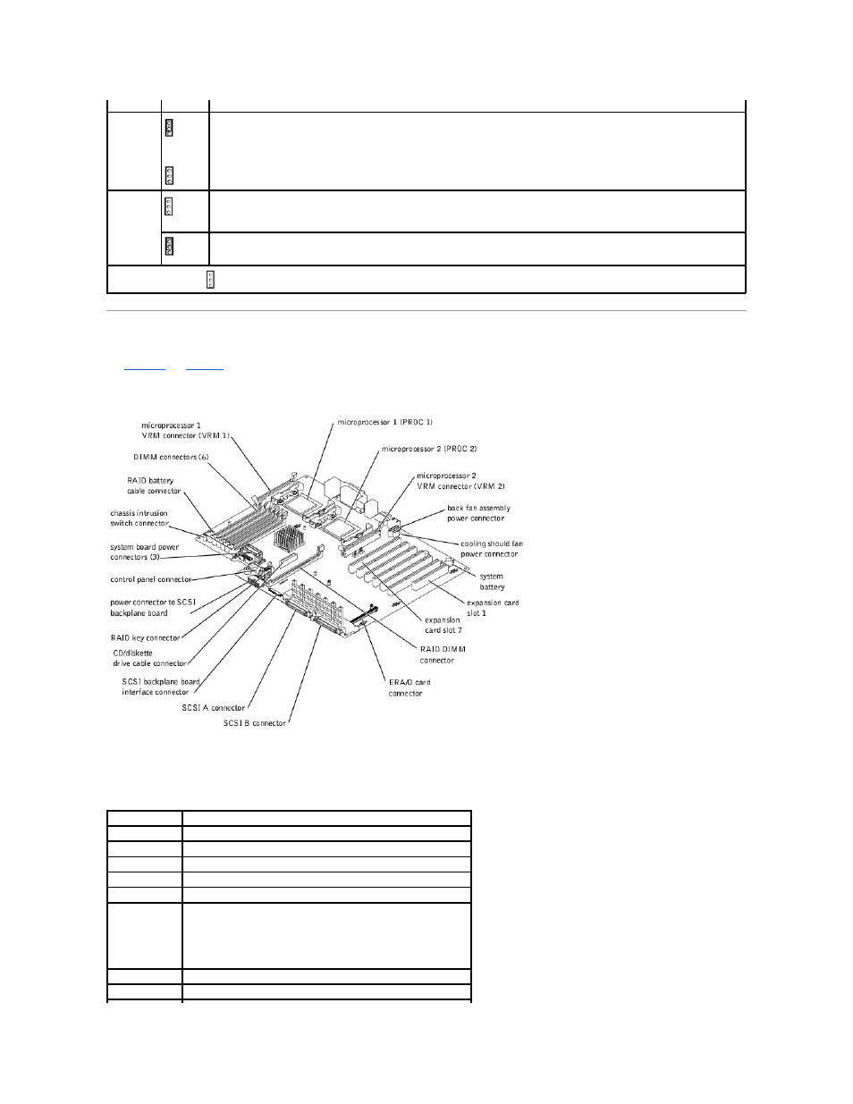
Figure 5-3. System Board Connectors
Table 5-2. System Board Connectors
Jumper
Setting
Description
PASSWD
(default)
The password feature is enabled.
The password feature is disabled.
NVRAM_CLR
(default)
The configuration settings are retained at system boot.
The configuration settings are cleared at next system boot. (If the configuration settings become corrupted to the point where the
system will not boot, install the jumper and boot the system. Remove the jumper before restoring the configuration information.)
jumpered unjumpered
Connector
Description
BACKPLANE
SCSI backplane board interface cable connector
BATTERY
System battery
CONTROL_PANEL System control panel connector
DIMM_nX
Memory modules (6), where n is the bank and X is the slot in the bank
ERA_CARD
ERA/O card connector
FAN_n
Cooling fan power connector:
l
1 — back fan assembly (fans 1 and 2)
l
2 — front fan assembly (fans 2 and 4)
l
3 — cooling shroud fan (fan 5)
IDE
CD/diskette drive interposer board power and data cable connector
POWERn
Power connectors