Cooling fan indicator codes, System beep codes, Table 3 – Dell PowerEdge 2600 User Manual
Page 11: Lists the era/o ethernet connector indicator codes
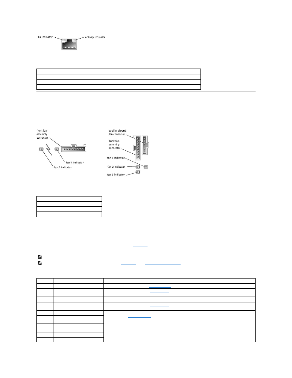
Table 3-8. ERA/O Ethernet Connector Indicator Codes
Cooling Fan Indicator Codes
locate the fan connectors on the system board, see
Figure 5
-2
. To locate the fan connector on the SCSI backplane board, see
Figure 5
-4
.
lists the
cooling fan indicator codes.
Figure 3-8. Cooling Fan Status Indicators
Table 3-9. Cooling Fan Indicator Codes
System Beep Codes
When an error that cannot be reported on the monitor occurs during a boot routine, the system may emit a series of beeps that identifies the problem.
When a beep code is emitted, make a note of it and then look it up in
. If you are unable to resolve the problem by looking up the meaning of the
beep code, use the system diagnostics to identify a more serious cause.
Table 3-10. System Beep Codes
Link Indicator Activity Indicator Indicator Code
Off
Off
The ERA/O Ethernet connector is not connected to the network.
Green
Amber
The ERA/O Ethernet connector is connected to a valid link partner on the network.
Green
Amber blinking
Network data is being sent or received.
Indicator
Indicator Code
Off
The fan is not installed.
Green
The fan is operating normally.
Amber blinking The fan is malfunctioning.
NOTE:
If the system boots without a keyboard, mouse, or monitor attached, the system will not issue beep codes related to those peripherals.
NOTE:
Before you perform any procedures described in
, see "
External Visual Inspection
."
Code
Cause
Corrective Action
1-1-2
CPU register test failure.
Replace microprocessor 0. See "
Microprocessors
." If the problem persists, replace microprocessor 1.
1-1-3
CMOS write/read failure; faulty
system board.
Replace the system board (see "
System Board
").
1-1-4
BIOS error.
Reflash the BIOS firmware. Download the latest firmware from the Dell Support website at support.dell.com.
1-2-1
Programmable interval-timer
failure; faulty system board.
Replace the system board (see "
System Board
").
1-2-2
DMA initialization failure.
Ensure that the memory modules are properly installed. If the problem persists, replace the faulty memory
module(s) (see "
Memory Modules
").
1-2-3
DMA page register write/read
failure.
1-3-1
Main-memory refresh verification
failure.
1-3-2
No memory installed.
1-3-3
Chip or data line failure in the first