Scsi backplane board, Removing the scsi backplane daughter card, Removing the scsi backplane board – Dell PowerEdge 2600 User Manual
Page 47
5.
Reconfigure the SCSI cable connections to the SCSI backplane as necessary to operate the backplane as a 2 x 3 split backplane:
An integrated RAID controller card is installed by default; no cables are required to use the integrated RAID controller in either the 1 x 5 or 2 x 3 split
configuration. See
Figure 5
-4
to locate the connectors on the SCSI backplane board.
6.
7.
Reconnect your system and peripherals to their electrical outlets, and turn on the system.
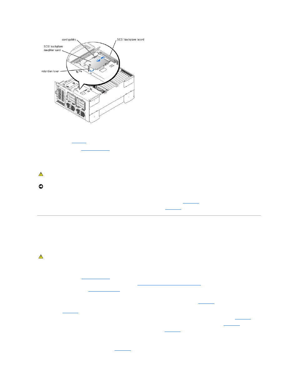
Removing the SCSI Backplane Daughter Card
1.
Turn off the system, including any attached peripherals, and disconnect the system from the electrical outlet.
2.
Pull the retention lever to slide the daughter card away from the SCSI backplane connector (see
).
3.
Lift the card up and away from the tabs on the card guide above the drive bay (see
).
SCSI Backplane Board
The system contains up to six 1-inch SCSI hard drives that connect to a controller on the system board or a RAID controller card through the SCSI backplane
board.
Removing the SCSI Backplane Board
1.
Turn off the system, including any attached peripherals, and disconnect the system from the electrical outlet.
2.
3.
Remove the SCSI backplane daughter card if it is installed (see "
Removing the SCSI Backplane Daughter Card
4.
Remove all hard drives (see "
").
5.
Disconnect the front fan assembly power cable from its P1 connector on the front of the SCSI backplane board.
6.
).
7.
Pull the locking bar to the unlock position to remove the flat cable connector (BKPLN) from the PLANAR CONNECTOR on the back of the SCSI backplane
board (see
).
8.
Disconnect the 14-conductor power cable from the SCSI BACKPLANE POWER connector on the back of the SCSI backplane board (see
).
9.
Disconnect the 4-conductor power cable from the 1 x 2 SCSI POWER connector on the back of the SCSI backplane board (see
10.
Loosen the thumbscrew that secures the SCSI backplane board in the system (see
).
11.
Slide the backplane board up about 0.5 inch.
12.
Pull the backplane board off of its grounding tabs.
13.
Lift the backplane board out of the system (see
CAUTION:
Only trained service technicians are authorized to remove the system cover and access any of the components inside the system. See
your System Information Guide for complete information about safety precautions, working inside the computer, and protecting against
electrostatic discharge.
NOTICE:
To avoid possible data loss, back up all data on the hard drives before changing the SCSI configuration.
CAUTION:
Only trained service technicians are authorized to remove the system cover and access any of the components inside the system. See
your System Information Guide for complete information about safety precautions, working inside the computer, and protecting against
electrostatic discharge.