Testing procedures, Test set up – Ames Fire & Waterworks 5000RPDA Reduced Pressure Detector Assemblies User Manual
Page 5
5
TESTING PROCEDURES:
SERIES 4000RP AND 5000RPDA
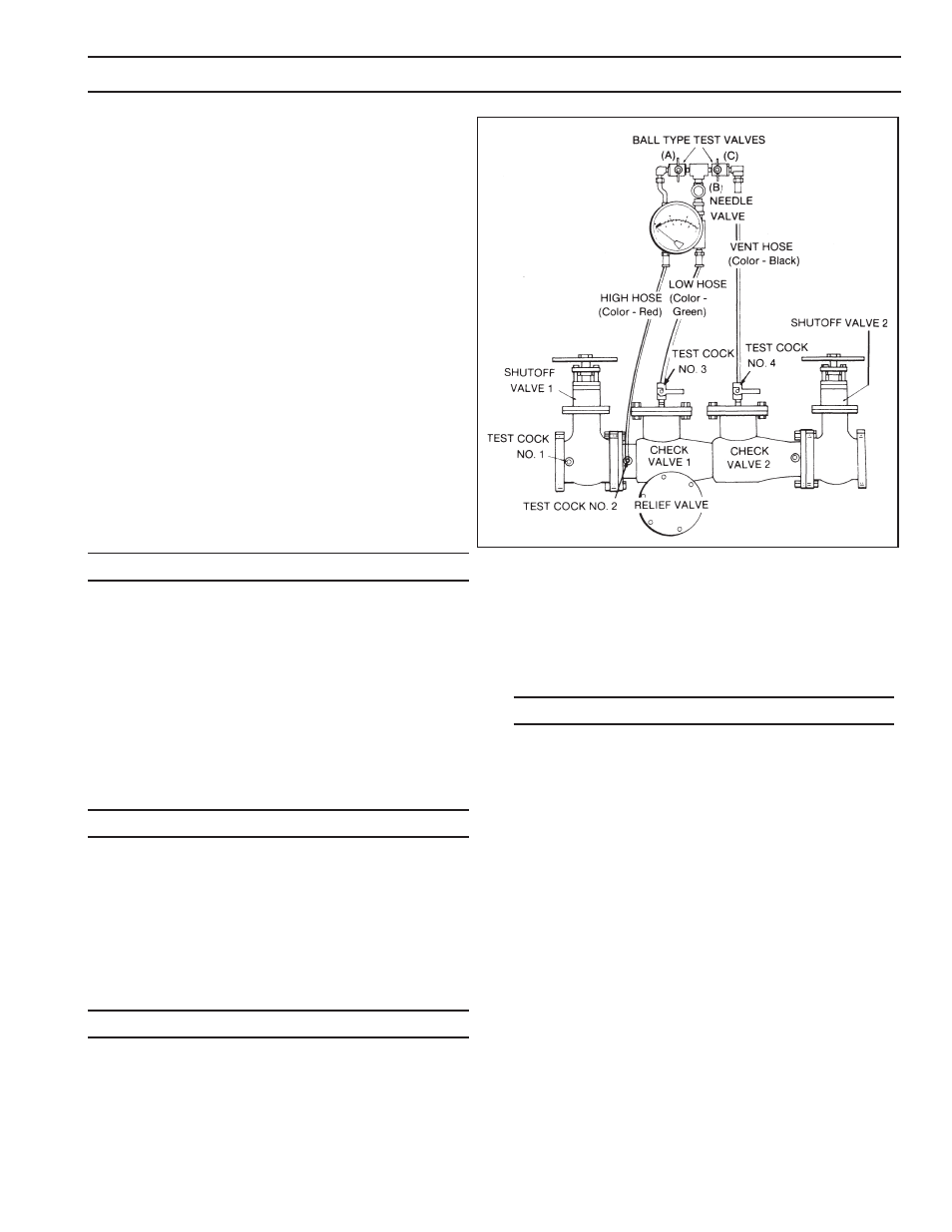
TEST SET UP
Close Valves (A), (B) and (C) on Test Kit.
Connect the No. 2 Test Cock of the device to
the “HIGH” Hose.
Connect the No. 3 Test Cock of the device to
the “LOW” Hose.
Close No. 2 shutoff valve of the device.
Open Test Cocks No. 2 and No. 3.
Open “Vent” (C) valve.
Open “High” (A) valve and bleed to atmosphere
until all the air is expelled.
Close the “High” (A) valve. Open the “Low” (B)
valve and bleed to atmosphere until all air is ex-
pelled. Close “Low” (B) valve. Close “Vent” (C)
valve.
Connect the No. 4 Test Cock of the device to the
“VENT” Hose.
TEST NO. 1
PURPOSE:
To test Check Valve No. 2 for tightness against re-
verse fl ow.
REQUIREMENTS:
Valve must be tight against reverse fl ow under all
pressure differentials. Slowly open the “High” (A)
and “Vent” (C) valves and keep the “Low” (B) valve
closed. Open the No. 4 test cock. Indicated pressure
differential will decrease slightly. If pressure differential
continues to decrease (until the vent opens) the No.
2 Check Valve is reported as “leaking”.
TEST NO. 2
PURPOSE:
To test Shutoff Valve No. 2 for tightness.
REQUIREMENTS:
After passing test No. 1 continue to test No. 2 by
closing test cock No. 2. The indicated pressure dif-
ferential will decrease slightly. If pressure differential
continues to decrease (approaching “zero”) the No.
2 Shutoff Valve is reported to be “leaking”.
TEST NO. 3
PURPOSE:
To test Check Valve No. 1 for tightness.
REQUIREMENTS:
Valve must be tight against reverse fl ow under all pres-
sure differentials. Close “High” (A) valve and open
Test Cock No. 2. Close Test Cock No. 4. Disconnect
“Vent” Hose at Test Cock No. 4. Open valves (B)
and (C) bleeding to atmosphere, then closing valve
(B) restores the system to a normal static condition.
Observe the pressure differential gauge if there is a
decrease in the indicated value, the No. 1 Check Valve
is reported as “leaking”.
TEST NO. 4
PURPOSE:
To test operation of pressure differential relief valve.
REQUIREMENTS:
The pressure differential relief valve must operate to
maintain the “zone” between the two check valves
at least 2 psi less than the supply pressure. Close
“Vent” (C) valve. Open the “High” (A) valve. Open the
“Low” (B) valve very slowly until the differential gauge
needle starts to drop. Hold the valve at this position
and observe the gauge reading at the moment the
fi rst discharge is noted from the relief valve. Record
this as the opening differential pressure of the relief
valve.
NOTE: It is important that the differential gauge
needle drops slowly.
Close Test Cocks No. 2 and 3. Use “Vent” Hose to
relieve pressure from test kit by opening valves (A),
(B) and (C). Remove all test equipment and open No.
2 Shutoff Valve of the device.