See drawing page 15) – Ames Fire & Waterworks 5000RPDA Reduced Pressure Detector Assemblies User Manual
Page 10
10
MAINTENANCE INSTRUCTIONS:
REMOVAL AND REPAIR OF RELIEF VALVE
(See Drawing Page 15)
DRAWING IV
1. Depressurize assembly. Disconnect hose and re-
move relief valve from elbow fl ange. Inspect rubber
relief valve mounting seat gasket for debris, cutting
or distortion of rubber. Remove
5
/
16
" lid bolts.
2. Disassemble piston assembly by unscrewing top
diaphragm plate from seat tube in counter clockwise
direction. Remove O-ring from relief valve body. Clean
and inspect all parts for damage, debris or buildup.
Clean and inspect vent hole in seat tube and O-ring
groove in body.
3. Place small amount of FDA approved lubricant on
O-ring groove, seat tube OD, O-ring guide pin and
diaphragm plate threads. (Do not use petroleum or
solvent based lubricant). Clean O-ring groove on top
washer plate. Hold top washer plate with threaded
side up. Set diaphragm on washer plate with side
marked HIGH PRESSURE SIDE down, install bottom
washer plate with spring guide shoulder away from
diaphragm. Set seat tube on threaded stub of washer
plate and slowly engage threads. Hand tighten seat
tube in clockwise direction.
4. Stretch to 3" diameter and lubricate O-ring and
place in O-ring groove. Place relief valve spring in
body. Place lid with bolts on piston assembly and
thread diaphragm over bolts. Ensure that diaphragm
is not pinched between lid and washer plate. Reas-
semble unit assuring spring is seated over guide and
that tube is carefully pushed through O-ring in body.
Hand tighten bolts. If O-ring has been pushed from
groove, disassemble, inspect for damage, and repeat
assembly.
Clean and place rubber seat mounting gasket in
recess with raised O-ring side out. Before installing
relief valve, slightly open #1 gate valve to ensure hose
if free of debris and debris is washed from main body.
Bolt relief valve to mainline valve and install hose.
Open #1 gate valve and bleed air from all test cocks
and air vents on relief valve.
5. Test assembly.
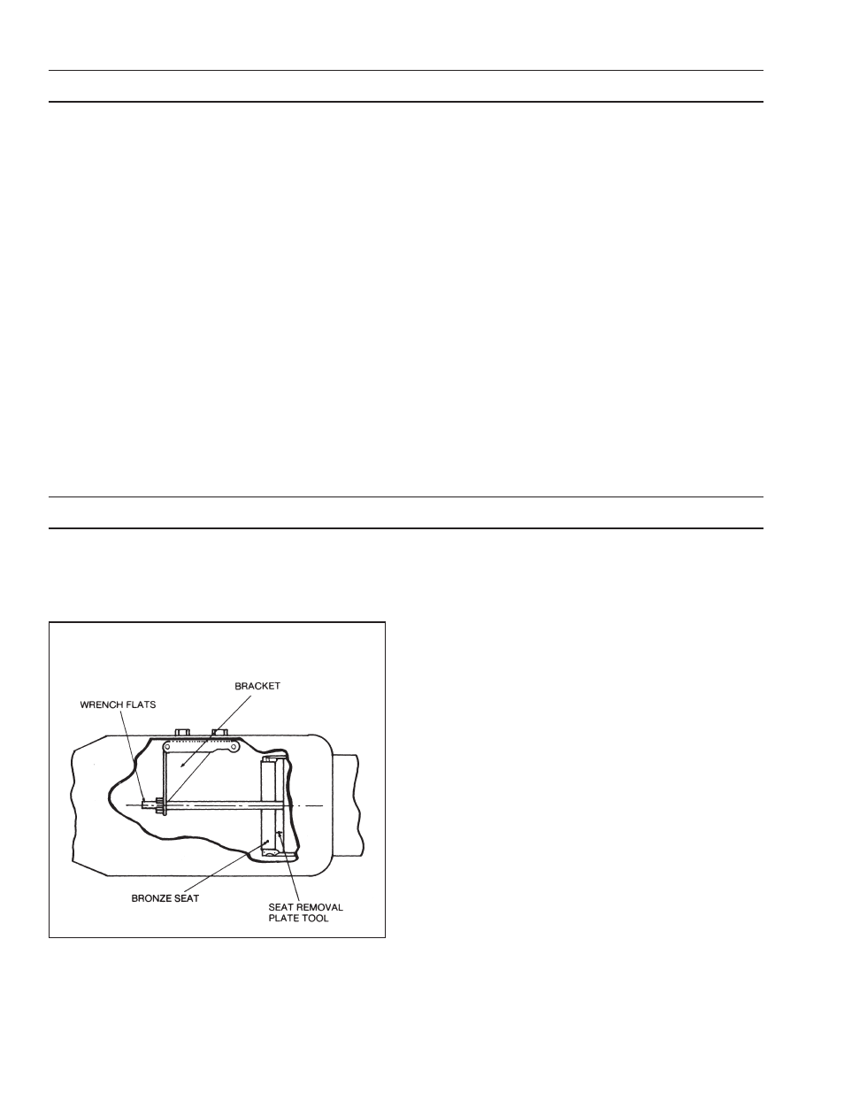
I. Removing Bronze Seat (all assemblies
except #1 RP, 8" and 10" (200-250mm)
DC and DCDC)
1. Remove knuckle joint assembly. (Instructions pg. 8)
2. Insert seat replacement bracket into interior of body
and install where knuckle joint was located.
3. Place seat removal tool beyond seat into pulling
position.
4. Install rod through bracket seat and thread into
seat removal tool.
5. Thread nut and washer onto rod until contact with
bracket.
6. Place wrench on rod fl ats, while using another
wrench to tighten nut until seat dislodges from
body.
7. Remove seat and all tooling except bracket from
body.