Edge Lighting Micro Switch User Manual
Micro switch, A typical cabinet installation diagram, Installation instructions for
SS-MSW
Installation Instructions for
Micro Switch
904-SS-MSW-01
1718 W. Fullerton Ave
Chicago, IL 60614
Tel: 773-770-1195
Fax: 773-935-5613
www.edgelighting.com
© 2010 Edge Lighting. All Rights Reserved.
SAVE THESE INSTRUCTIONS!
- This instruction shows a typical installation.
- Micro switch is normally closed momentary switch that is
rated for 12A, 125V AC.
IMPORTANT INFORMATION
A
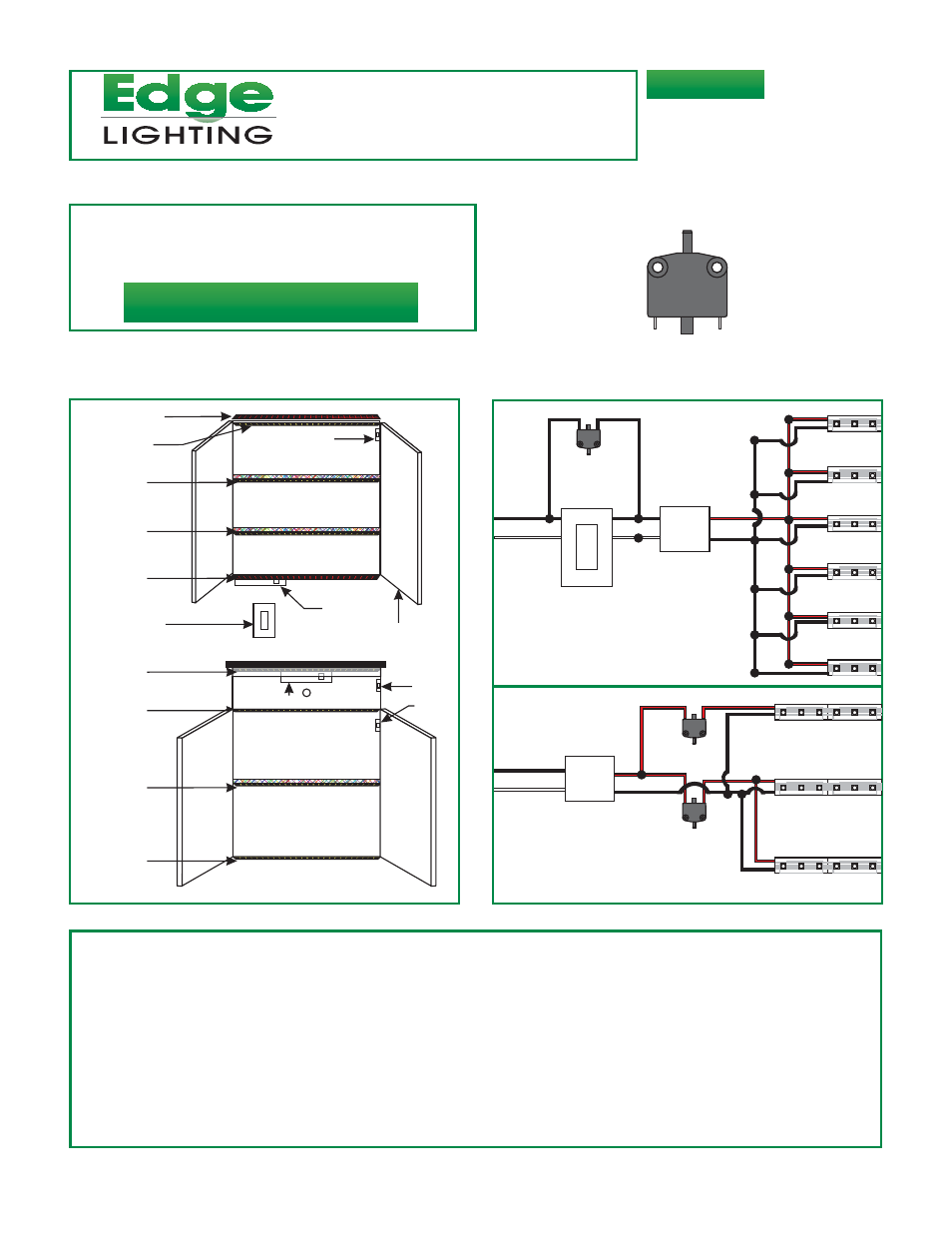
A Typical Cabinet Installation Diagram
SS# 9
SS# 8
SS# 7
SS# 6
SS# 5
SW# 3
PS# 2
SW# 1
SS# 4
SS# 3
SS#2
SS# 1
SW# 2
PS# 1
Electronic Low
Voltage Dimmer
L
N
-
+
SS#9
SS#8
120VAC
INPUT
L
N
SS#7
SS#6
SS#5
SS#1
SW#3
Electronic Low
Voltage Dimmer
PS#2
12VDC
OUTPUT
L
N
SW#1
SS#2
120VAC
INPUT
PS#1
-
+
12VDC
OUTPUT
SS#1: Tow kick soft strip.
SS#2 & SS#3: Bottom cabinet soft strips.
SS#4: Drawer soft strip.
SS#5: Under Cabinet soft strip.
SS#6, 7, & 8: Upper Cabinet glass door soft strips.
SS#9: Top of the Cabinet soft strip.
PS#1: PS-60-12VDC, PSB-60-12VDC, or TEB-60-12DC installed behind one of the drawer.
SW#1 & SW#2: Micro switches used in low voltage side to turn the SS#2, SS#3 & SS#4 on when the drawer or cabinet
doors are opened.
PS#2: TEB-60-12DC used with electronic low voltage dimmer to dim the SS#1, SS#5, SS#6, SS#7, SS#8, and SS#9.
SW#3: Micro switch is used in line voltage side to bypass the dimmer and turn to top cabinet soft strips to full power when
the cabinet doors are opened.
GLASS
DOOR
SS#3
SS#4
SW#2