Connecting the channel, Install the channel – Edge Lighting Cirrus Channel, Square 1" Lens User Manual
Page 2
2
D
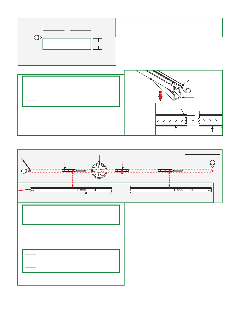
4"
9
8: Mark a 4" x 0.7" rectangle on drywall where the electrical
box opening will be located.
9: Cut out the marked square(s) and install the drywall.
0.7"
DRYWALL
Connecting the Channel
JOINER
BRACKET
CHANNEL
E
1
LENS
JOINER CHANNEL
MALE
CONNECTOR
FEMALE
CONNECTOR
CHANNEL
1: Lift a section of the lens at the end of the channels where
the connectors are visible. Slide the channel over the joiner
bracket make sure that the male & female connectors mate
properly.
2: Push the lens back into the channel.
NOTE:
piece (120" or less).
Omit this section if the channel is made out of a single
NOTE:
Prior to installation, Cirrus Channel must be connected to
one another to make proper measurements on surface for
markings.
NOTE:
It is recommended more than one person to assist in this
installation
Install the Channel
F
POWER FEED END
OF CHANNEL
CHANNEL
END
BOTTOM OF CHANNEL
JUNCTION BOX
MOUNTING
CLIP (C-MCL)
RECEIVING BRACKET
MARKING LOCATION
1: Lay the channel to the desired location & make all necessary
markings which will consist of the channel ends, locking clips
and mounting clips. Mounting clips must be installed every
20" from each locking clip, locking mounting clips are not
necessary for channels under 2ft.
LOCKING CLIP
LOCKING CLIP
1
1
NOTE:
Remote power supply must be installed within 40ft of
electrical box. The low voltage 24V DC wires must be present in
electrical box before installing the channel. Refer to the
installation instructions provided with the power supply.
NOTE:
If the receiving bracket interferes with the electrical box,
then relocate the bracket by loosening the set screws and make
the necessary adjustments.
NOTE:
The channel must pass through the center of the
electrical box.
EVERY 20 INCHES
2: After all markings and required measurements are done, take
apart channels from each other.