Edge Lighting Bardot Vanity User Manual
Page 3
3
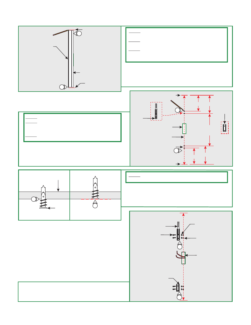
Section Three: Install Fixture For Both Versions
1: Align the channel to the junction box opening. Make
markings to each end of the channel and also make a center
line from end to end. Note which side the wires are
located to later install the locking clip to the opposing
side.
I
WALL
MARK LOCATION
MARK LOCATION
JUNCTION
BOX
1
1
CHANNEL
NOTE:
It is recommended more than one person to assist in
this installation.
NOTE:
Fixture can be mounted in a horizontal or vertical
position.
NOTE:
The junction box does not need to be in middle of the
channel (could be at either end) but needs to be aligned in the
center of the channel.
J
EXISTING MARK
JUNCTION
BOX
6 5/8" 7 5/8"
LOCKING
CLIP
3-3/4"
2
MARK
CENTER LINE
WALL
2
2-3/4"
EXISTING MARK
MOUNTING
CLIP
20" TYP.
2: From the two existing marks, make additional marks by
following drawing H (a typical suggested location with
measurements for the locking clip - longer runs contain two
locking clips) to install the locking & mounting clips properly.
Mounting clips must be installed every 20" from each other.
NOTE:
BV12-1RE shown for demonstration purposes
NOTE:
Locking clip must be installed in the opposite direction
of the fixture wire. Fixtures greater than 36" are provided with
two locking clips.
NOTE: T
he junction box could be offset, but needs to be
aligned to the center of the channel.
ANCHOR
ANCHOR MUST
BE FLUSH TO WALL
K
CEILING
3
4
3: Tap the anchors onto the marked points up to the threaded
portion with a hammer.
4: Screw in the threaded portion of the anchors with a Phillips
screwdriver.
NOTE:
if mounting the clips to a wood surface directly.
Steps 3 and 4 are for drywall mounting. Omit these steps
5: Secure the locking clip(s) & mounting clip(s) to the marked
surface or anchors by passing the screws through the clip
holes followed by the washers into the marked points or
anchors. Locking clips mount onto mounting clips.
L
WALL
MOUNTING
CLIP
5
#6 SCREW
ELECTRICAL BOX
LOCKING CLIP
5
WASHER
MARKED
POINT/ANCHOR