Edge Lighting Vessel 16 - Fluorescent GU24 User Manual
Page 2
2
D
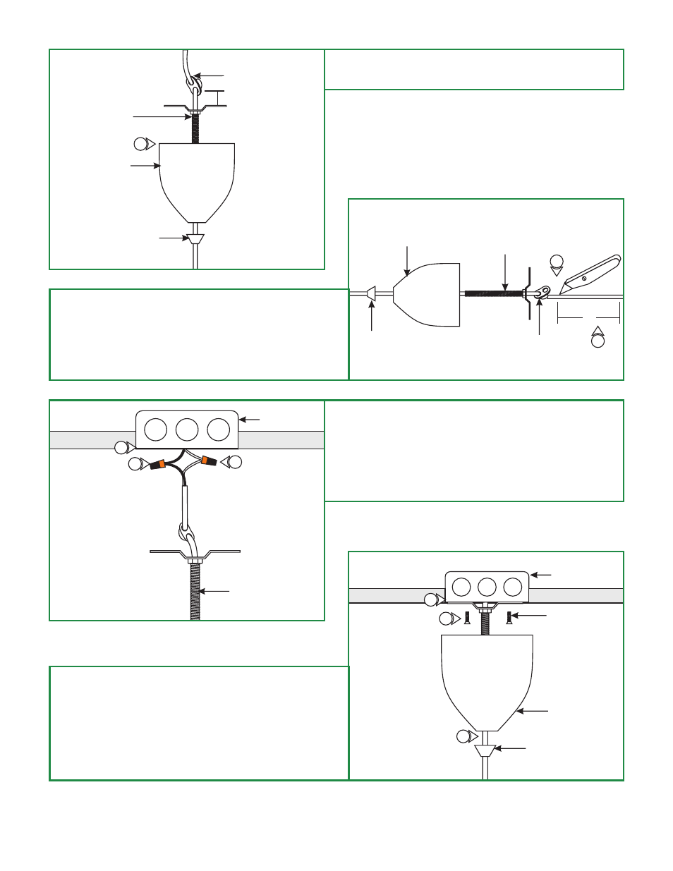
4: Place the cord clip 1" above the marked line by feeding
the cord through the second hole on the cord clip and
pulling it out to lock in place.
CANOPY
CROSSBAR
ASSEMBLY
THREADED CAP
CORD CLIP
4
1"
E
4"
5: Leave 6" of the cord behind the crossbar assembly for
power connections. Cut the excess cord.
6: From the end of the cord remove 4" of the cord
insulation.
7: Strip 1/4" of the insulation from the end of the wires.
CANOPY
CROSSBAR
ASSEMBLY
THREADED
CAP
CORD CLIP
5
6
F
8:
9: Connect the fixture white wire to the neutral power wire
with a wire nut.
10: Connect the fixture black wire to the hot power wire with
a wire nut.
Make sure that the canopy is grounded in accordance
with local electrical codes.
10
9
ELECTRICAL
BOX
CROSSBAR
ASSEMBLY
G
11:
12: Mount the crossbar assembly to the electrical box holes
with the provided two #8-32 screws.
13: Slide the canopy up onto the crossbar assembly and
secure it in place by tightening the threaded cap to the
crossbar assembly nipple.
Place all wires and wire nut connections inside the
electrical box.
ELECTRICAL
BOX
#8-32 SCREWS
11
12
CANOPY
THREADED CAP
13
8