Xcell shockpod shockpod connectors power switch – Bio-Rad Gene Pulser Xcell™ Electroporation Systems User Manual
Page 11
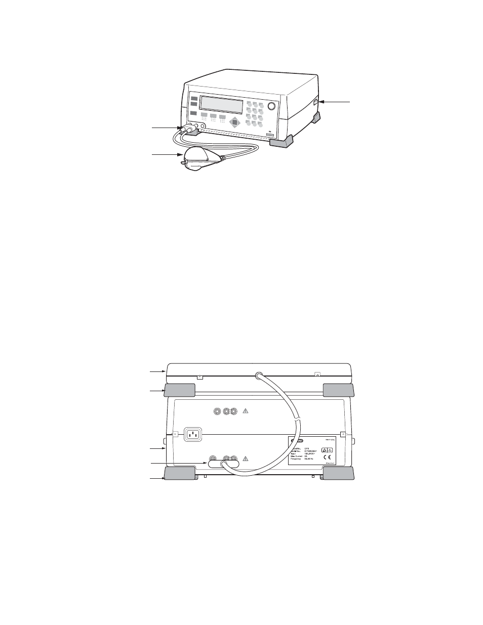
Fig. 2.2. Connecting the ShockPod to the Gene Pulser Xcell main unit.
2.2.2
Connecting the PC Module to the Gene Pulser Xcell Main Unit (Cat. #s 165-2660,
165-2662, and 165-2668)
The PC Module and CE Module may be connected to the Gene Pulser Xcell main unit in any order and
both may be connected at the same time. Before connecting the PC Module to the Gene Pulser Xcell,
be sure that the Gene Pulser Xcell is turned off. There is no power switch on the PC Module; it is
controlled entirely by the Gene Pulser Xcell main unit.
1.
Place the PC Module near the Gene Pulser Xcell main unit. The units, along with the CE Module,
are stackable; either the PC Module or the Gene Pulser Xcell main unit can be placed on the bottom.
Place the feet of the top unit at the corners of the bottom unit to interlock the two.
2.
Insert the red/black connector that is permanently attached to the cable on the back of the PC
Module into the appropriately labeled receptacle on the back of the Gene Pulser Xcell main unit
(see Figure 2.3). The connector is keyed so that it will insert only into the proper receptacle and in
the correct red/black orientation.
Fig. 2.3. Rear view (back panel) of PC Module showing the connection to the Gene Pulser Xcell
main unit.
CE MODULE
PC MODULE
POWER INLET
Foot
Xcell PC Module
Xcell Main Unit
Foot
Connections to
PC Module
1
2
3
4
5
6
7
8
0
9
Xcell ShockPod
ShockPod
Connectors
Power Switch
5