4 optical filters, 1 standard filter configuration – Bio-Rad S3™ Cell Sorter User Manual
Page 72
Acquisition
62 | S3 and S3e Cell Sorters
11. Place the container back into position.
12. Attach the quick disconnect to the cap assembly. An audible click should be heard.
13. Click the play button in the Swap Fluidics window to finish the swapping procedure.
IMPORTANT!
n
When handling sheath fluid and DI water containers, minimizing air exposure will
help to avoid contamination
n
While transferring cap assemblies to a new container, avoid touching the
assembly to outside surfaces of the containers. If it is necessary to set the cap
assembly down, use only sterilized surfaces
n
Treat all waste as biohazardous for safety
5.4 Optical Filters
The optical filters separate and direct the fluorescent light to the PMTs for detection. These filters
are located behind a sliding panel on the top and toward the rear of the S3 or S3e System.
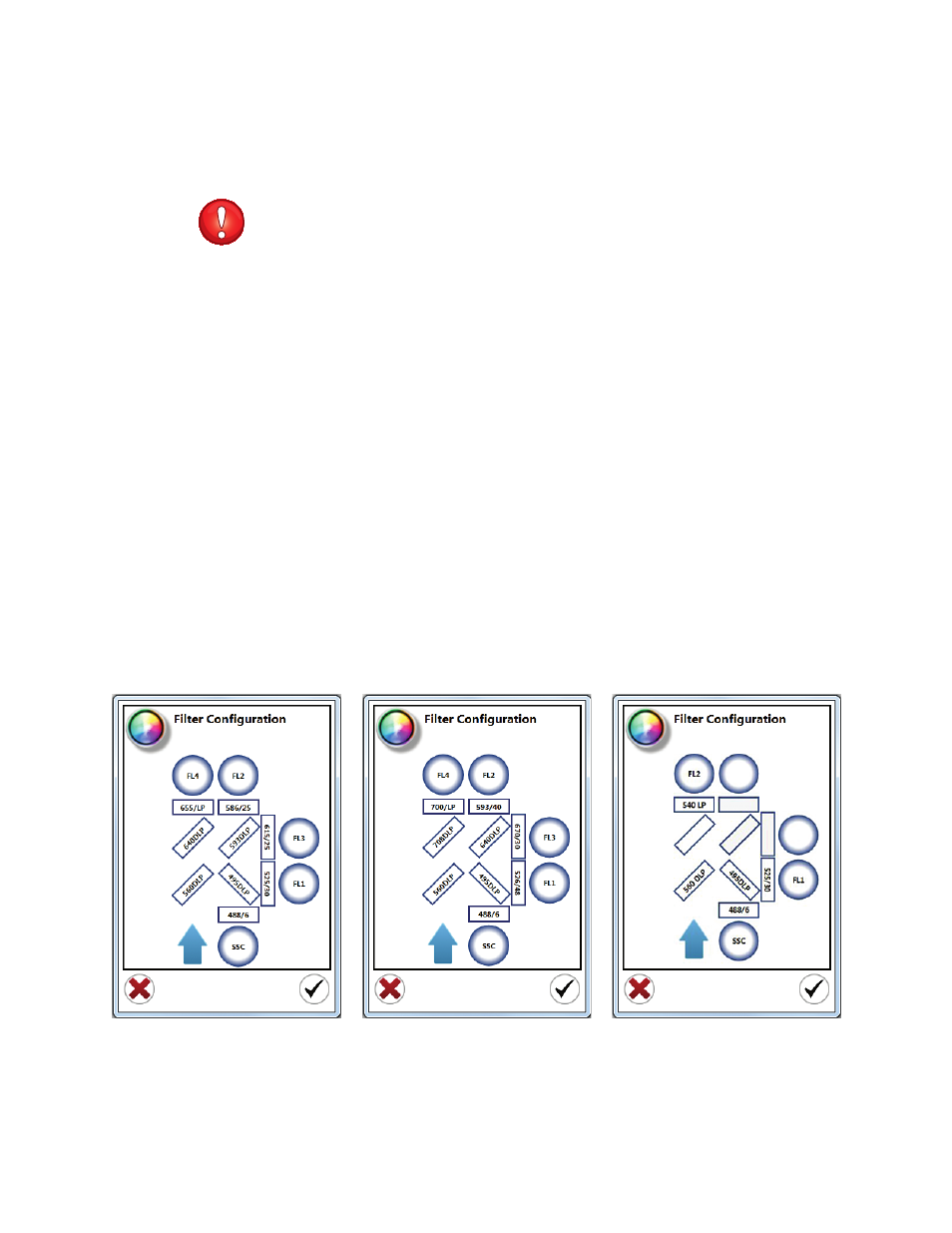
5.4.1 Standard Filter Configuration
The standard filter configurations for the S3 or S3e Systems are shown in Figure 68. The filter
configuration can be viewed and edited in the ProSort
™
Software.
To view or edit the filter configuration:
1. On the Setup and Maintenance tab select Filter Configuration.
2. Click inside each area to modify the filter name or wavelength.
3. Click the checkmark button to save the changes.
WARNING! Changes to the filter configuration will be set as the default.
Fig. 68. Different filter configurations. A, 488/561 nm system; B, 488/640 nm system; C, 488 nm system.