4 –basestation 3200 interface, Controller front panel layout – Baseline Systems BaseStation 3200 User Manual
Page 41
BaseStation 3200 Advanced Irrigation Controller Manual
4 –BASESTATION 3200 INTERFACE
Review this section to get familiar with the layout of the BaseStation 3200 interface. This information covers the
components of the front panel, the on-screen help, the features of the main screen, as well as the status colors
and a brief overview of the on-screen reports.
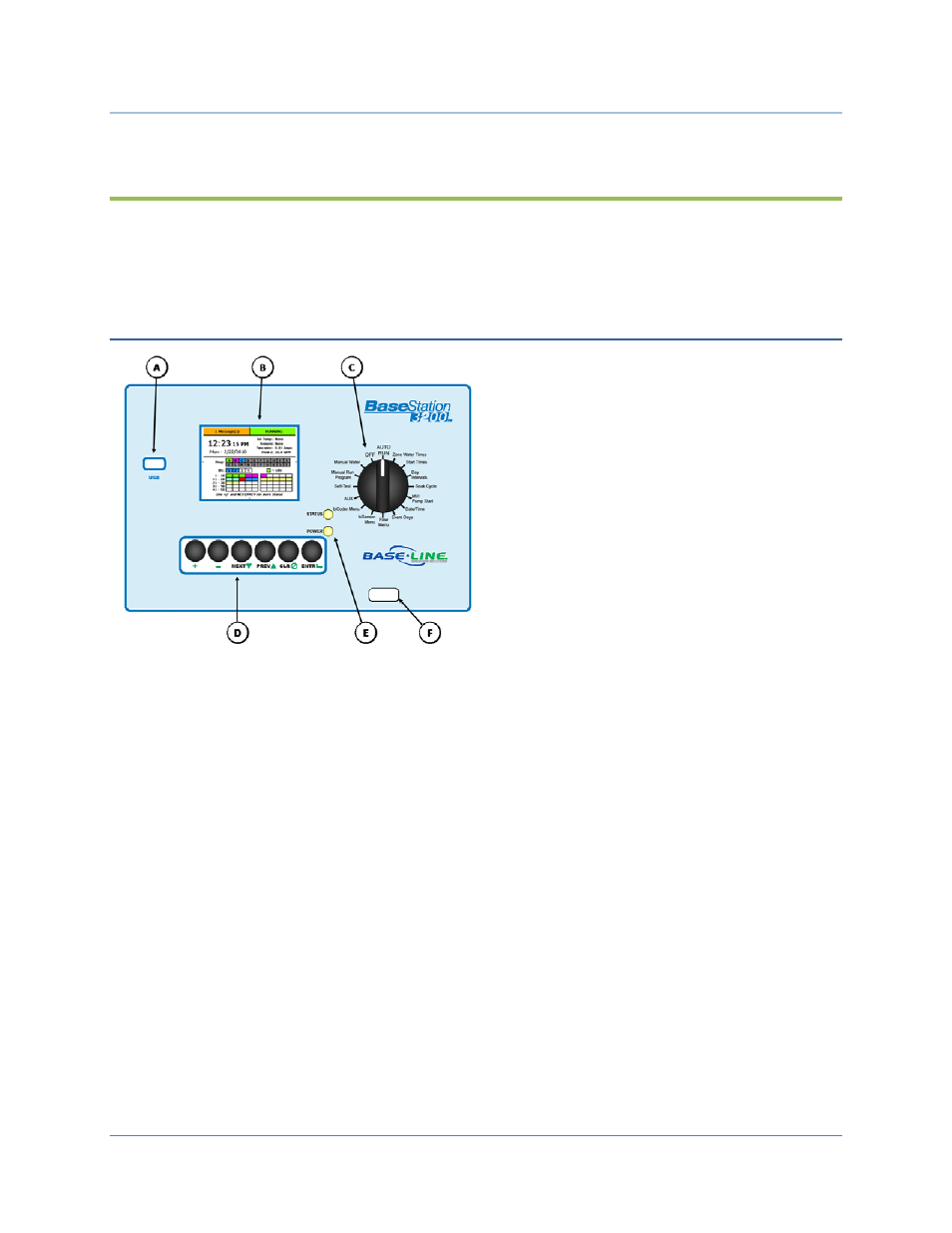
Controller Front Panel Layout
(A) USB Port – The USB port is used for doing Backup
and Restore operations using a USB drive (also known
as a “thumb drive” or a “flash drive”). The USB port is
also used for doing software updates and retrieving
operation log files.
(B) Display – The color display indicates the current
state of the controller and is used to display
programming. This display uses thin-film transistor
(TFT) technology to improve image quality in outdoor
conditions including direct sunlight and low light.
(C) Dial – The dial is used to select the operation or
programming mode of the controller.
(D) Buttons – The buttons are used to select programming elements, change their values, and initiate operations
like testing a zone.
+
Increases the value of the highlighted field or sequences through the available options in the
selected field
-
Decreases the value of the selected field, or sequences through the available options in the
selected field
NEXT
Moves the highlighted selection to the next field on the display
PREV
Moves the highlighted field selection to the previously selected field on the display
CLR
Performs the function indicated at the bottom of the display, normally a “clear” or “halt”
operation
ENTR
Saves the setting of the current selection and moves to the next item, or begins the
operation. Read the text at the bottom of the display for specific details.
(E) Status LEDs – These two LEDs indicate the power status of the controller and the internal status of the
controller hardware. The upper light is normally ON, but it may blink when internal diagnostics are run.
(F) Remote Control Port – This connector is used with the BL Commander hand-held radio remote control to
operate valves while away from the controller.
Page
33