Point row switches, When not planting or calibrating, Normal full pass – Great Plains 3N-4025P Operator Manual User Manual
Page 38: Point row in pass, Point row cal mode, Mr c l cal f s p
34
3N-40P
Great Plains Manufacturing, Inc.
196-538M
2014-01-29
Point Row Switches
The hydraulic drive motor operates whenever the speed
radar detects motion. The Point Row system determines
whether or not that motion is coupled to the meter drives,
by controlling the electric clutches. The implement lift
switch is part of the Point Row system.
A Point Row troubleshooting chart is found on page 129.
Refer to Figure 35
Note: The Pump
switch has no function on 3N-40P
drills configured by Great Plains. Unless connected
to aftermarket equipment, leave it off.
When Not Planting or Calibrating
Set the Master switch
OFF when you do not intend to
meter seed.
Entanglement Hazard:
If the hydraulic drive system is on, and the drill is lowered (or
the Master switch is in CAL), unexpected motion of chains,
sprockets, shafts and seed meters can occur if the speed radar
detects motion, such as someone moving near the radar.
Normal Full Pass
1.
Set Master switch
ON (up)
Set all sections
ON (up).
Check that corresponding lamps are on.
2.
Height switch automatically energizes clutches when
row units are lowered.
Point Row in Pass
3.
Turn desired sections off as non-planting regions are
reached.
4.
Turn the sections back on before commencing next
full-width pass.
Point Row CAL Mode
When the drill is raised, the lift switch normally causes
the Point Row Monitor to disengage the clutches for each
drill section. To keep one or more clutches engaged
during hydraulic drive calibration, set the Master switch
to CAL.
For a typical 3-row calibration, set the Left section
switch
on, and the center and right section
switches
/
off during calibration.
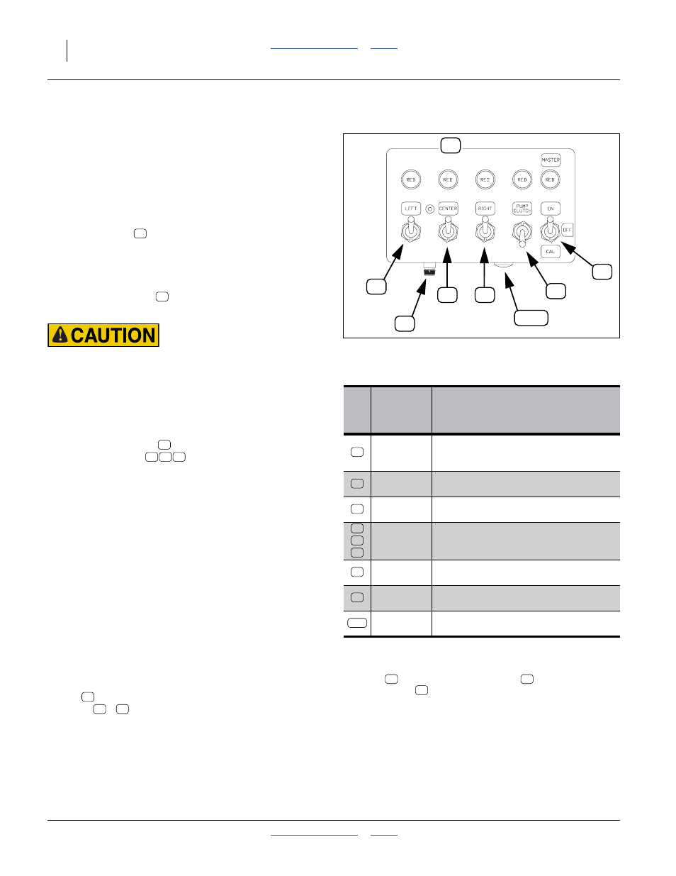
Figure 35
Cab Switch Box
28246
Switch
or
Indicator
Function
MASTER
Switch
Up: ON: System enabled
Center: OFF System inactive
Down: CAL: Lift switch bypassed on
MASTER
Lamp
On: System enabled
Off: System OFF
Section
Lamps
On: Clutch enabled for that section.
Off: Clutch not energized
a
a. However, the section’s meters may still be coupled
to the drive system, if lock-up bolts are installed in
the clutch. See page 149.
LEFT
CENTER
RIGHT
Up: section enabled
Down: section disabled
PUMP
May control customer-provisioned
equipment.
Fuse
b
b. If
lamp fails to illuminate with
set ON, check
the fuse
. If open, check for damaged cable /
failed clutch.
Protects switch box, clutches and
battery.
CAL Lamp
On: Lift switch overridden
Off: Lift switch active (or system off)
M
m
S
L
C
R
P
F
m
M
F
CAL
M
R
C
L
CAL
F
S
P
{
P
M
M
L
C R
L
C
R