Great Plains 3N-4025P Operator Manual User Manual
Page 116
112
3N-40P
Great Plains Manufacturing, Inc.
196-538M
2014-01-29
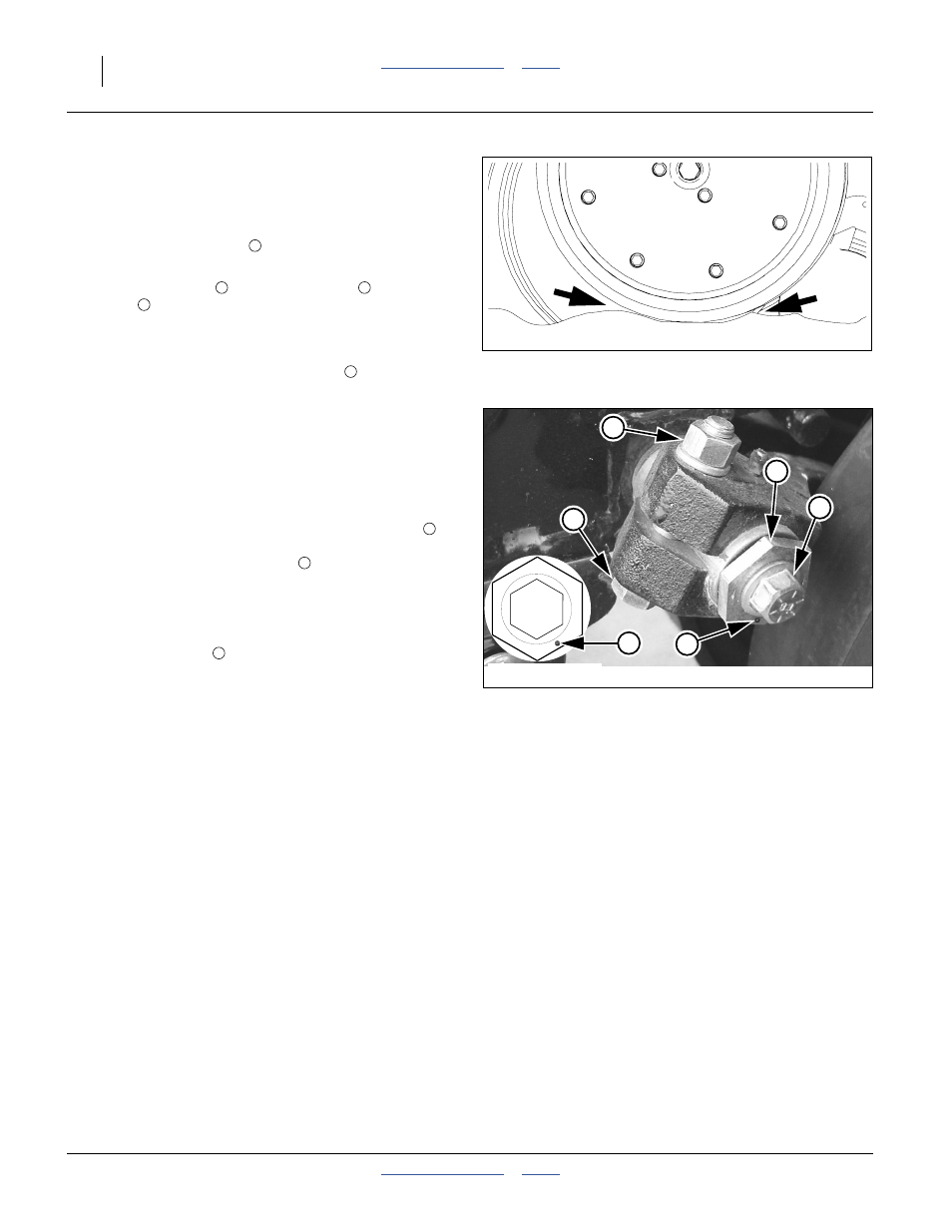
Refer to Figure 157
To adjust side gauge wheels:
1.
Raise planter slightly removing weight from side
gauge wheels.
2.
Loosen hex-head bolt
. Move wheel and arm out
on O-ring bushing.
3.
Loosen pivot bolt
. Turn hex adjuster
so indicator
notch
is at 5 o’clock to 7 o’clock.
Note: Use this as the starting point for adjustment.
4.
Move wheel arm in so side gauge wheel contacts
row unit disk. Tighten hex-head bolt
around bushing and shank.
5.
Check wheel-to-disk contact at 2 inch planting depth.
Lift wheel 2 inch and release. When let go, wheel
should fall freely.
• If wheel does not contact disk at bottom to area where
blade leaves contact with soil, move hex adjuster until
wheel is angled for proper contact with disk.
• If wheel does not fall freely, loosen hex-head bolt
and slide wheel arm out just until wheel and arm move
freely. Retighten hex-head bolt
per grade:
1
⁄
2
inch Grade 5 bolt, 75 ft-lbs.
1
⁄
2
inch Grade 8 bolt, 110 ft-lbs.
6.
Keep turning hex adjuster and moving wheel arm
until the wheel is adjusted properly. When satisfied,
tighten pivot bolt
Note: Use “Torque Values Chart” on page 175 for
reference.
Figure 156: 20 Series:
Opener-Gauge Wheel Contact
22531
Contact Within this Area
1
Figure 157: 20P Series:
Disk/Gauge Wheel Adjustment
22524
22525
Starting Point
4
1
2
3
1
2