Openers – Great Plains PT1230 AA1062 Operator Manual User Manual
Page 49
47
Section 7 Maintenance and Lubrication
PT1230 Pull-Type Folding Planter 401-069M-A
10/10/12
Great Plains Mfg., Inc.
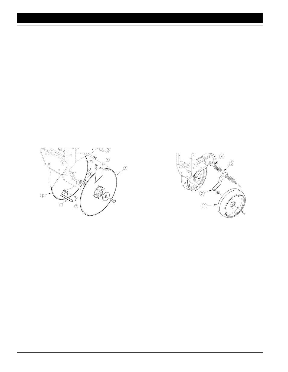
Openers
1.
With the unit raised, check the blade scraper (1) for
wear. Replace the scraper if it is 1/2 inches wide or
narrower. To replace, remove a side gauge wheel and
disk blade. Drive out the roll pin (2) and install a new
scraper.
2.
Check the disk blades (3) for wear. To maintain proper
planting depth, replace if worn to a diameter of 14 1/2
inches or less.
3.
When re-installing disk blades, put three shims be-
tween the bearing and cast-iron shank on one blade.
Tighten bolt. On the opposite side, re-install blade with
two (4) shims between the bearing and cast-iron
shank. Tighten bolt.
4.
Check that the outside disk scrapers (5) are formed to
the disk blades to help remove any mud. Bend and
twist the scrapers to fit the blades as necessary.
Check outside scrapers for proper adjustment and
wear every 200 acres. Replace outside scrapers as
necessary.
16846
Opener Maintenance
Figure 7-12
5.
Check the contact point between the two disk blades.
Place a piece of paper in the top gap between the
disks blades. Bring the paper down until it stops. In the
lower gap place another piece of paper. Bring up until
it stops. Measure the distance between the two pieces
of paper. The distance must be between 1/2 and 1 3/
4 inches. Add or remove shims as needed to get the
correct contact point.
6.
Check for the correct number of shims between the
side gauge wheel (1) and the wheel arm (2). There
must be at least one shim between the wheel bearing
and arm. When installed, the wheel should turn freely
and not hit the arm at the curve. Do not add any more
shims than necessary.
7.
Disassemble the side-gauge-wheel arm (2) from the
row unit. Check the arm and bushing (3) for build up of
grease and dirt in the grease groove. Clean as need-
ed. Re-install as follows:
a.
Place the bushing (3) on stem sticking out of row
unit (4).
b.
Place at least three shim washers over bushing.
c.
Slide the gauge wheel arm on the bushing, push-
ing it up to the shims.
d.
Place shim washers on the bushing until even with
the end of the bushing.
e.
Secure side gauge wheel to arm with a 1/2-inch
bolt, lock washer and flat washer. Tighten to 76
foot-pounds.
16847
Side Gauge Wheel Assembly
Figure 7-13
f.
Check the distance between the side gauge
wheel and the disk blade at the bottom of the
wheel and blade. The distance between the wheel
and blade must be no greater than 1/8 inch. Place
the T- handle in the lowest hole possible, then lift
the wheel and arm. When let go, the wheel should
fall freely. If the wheel is not close enough to the
blade or the wheel does not fall freely, reposition
shims until corrected.
8.
Install the arm and the shims onto the spindle. Tighten
1/2" bolt to the correct torque value as listed in the
Torque Values Chart in “Appendix” on page
9.
Check clearance or contact of the tire and disk. The
gauge wheel should fall freely when lifted. Repeat
steps 1 through 4 if necessary.