Unfolding, Danger – Great Plains PT1230 AA1062 Operator Manual User Manual
Page 15
13
Section 2 Planter Operation
PT1230 Pull-Type Folding Planter 401-069M-A
10/10/12
Great Plains Mfg., Inc.
6.
After wings are off the ground, lower planter. This will
retract the wing gauge wheels. The cylinder locks will
keep planter from lowering to the ground.
IMPORTANT: It is important that the wing gauge
wheels are retracted before continuing to fold the
planter. Failure to retract wheels will lead to hopper
damage.
7.
Continue folding until wings are positioned above the
planter main frame.
Unfolding
!
DANGER!
Keep others away during unfolding operations. Do not walk un-
der wings when unfolding planter. See Figure 2-6 on page 14
before attempting to unfold planter.
Unfolding is best achieved on level ground with the tractor
transmission in neutral. Be aware of the clearance re-
quired to unfold the planter.
!
DANGER!
Keep clear of overhead power lines when unfolding planter
and/or markers.
NOTE: If unfolding planter with hoppers fully loaded, you
will need a tractor with at least 1900 psi hydraulic pres-
sure.
1.
Make sure hydraulic selector valve is in the “Road” po-
sition. See Figure 2-1 on page 12.
IMPORTANT: If the planter has set in the folded po-
sition for awhile, be sure the wing gauge wheels are
fully retracted before beginning to unfold planter. If
wheels are not retracted hopper damage will occur
when unfolding planter. Retract wheels by lowering
planter on transport locks.
2.
Begin to unfold planter.
3.
When wings have cleared the outside hopper on the
center section, raise planter. This will lower the wing
gauge wheels.
IMPORTANT: Make sure the wings have cleared the
outside hopper on the center section before raising
the planter. If raised too soon, the gauge wheels will
cause hopper damage.
4.
Continue unfolding planter.
5.
When wing gauge wheels contact the ground, pull
planter ahead a few feet while continuing to lower.
This will level wings.
6.
Remove the cylinder locks by removing the bent pins
and pivoting the locks off the cylinders. Replace the
bent pin to keep the locks off the cylinder.
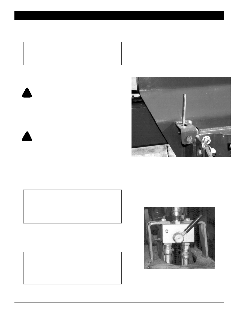
7.
Position arm wing lock pins as shown, see Figure 2-4
.
If wings are not level, it may be necessary to pull for-
ward a few feet to lock wing lock pins.
Arm Wing Lock Pin in Locked Position
Figure 2-4
15861
8.
Connect drive shaft by removing keeper pin on one
end of the drive shaft. Slide drive shaft together and
reinstall keeper pin.
9.
Before operating planter be sure to place hydraulic se-
lector valve in “Field” position. See Figure 2-5.
Hydraulic Selector Valve in “Field” Position
Figure 2-5
15862