Contact drive wheel spring, Meter drive adjustments, Check for vertical alignment – Great Plains PT1230 AA1062 Operator Manual User Manual
Page 27: Check for horizontal alignment, To adjust alignment
25
Section 4 Adjustments
PT1230 Pull-Type Folding Planter 401-069M-A
10/10/12
Great Plains Mfg., Inc.
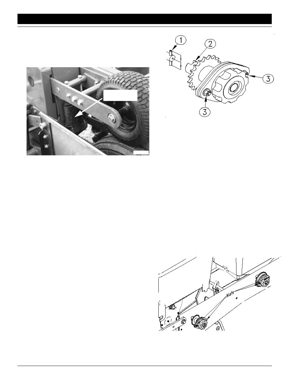
Contact Drive Wheel Spring
There are two down pressure springs, see Figure 4-3, on
each contact drive wheel. The down pressure is factory
preset and should need no further adjustment.
Meter Drive Adjustments
The alignment between the meter clutch and the input
shaft is important. If there is misalignment the meter will
not function properly. Excessive wear and damage can
also occur to the meter housings. When replacing the
meter the vertical and horizontal alignment should be
checked.
Check for Vertical Alignment
Refer to Figure 4-4:
1.
Latch the appropriate hopper into place on the sup-
port.
2.
The roll pin in the end of meter input shaft should be
centered (equal distances of the roll pin should pro-
trude from both sides of the shaft).
3.
Rotate the input shaft so that the roll pin is vertical.
4.
Rotate the drive coupler so that the slots are vertical.
5.
Release the clutch to engage the drive coupler with
the input shaft.
If the alignment is correct the coupler will engage with the
shaft freely and the roll pin will extend equally on each side
of the coupler. Disengage the clutch and check the hori-
zontal alignment.
Contact Drive Wheel Spring
Figure 4-3
15882
Contact Drive
Wheel Spring
Check for Horizontal Alignment
Refer to Figure 4-5:
1.
Latch the appropriate hopper into place on the hopper
support.
2.
The roll pin in the end of meter input shaft should be
centered (equal distances of the roll pin should pro-
trude from both sides of the shaft).
3.
Rotate the input shaft so that the roll pin is horizontal.
4.
Rotate the drive coupler so that the slots are horizon-
tal.
5.
Release the clutch to engage the drive coupler with
the input shaft.
To adjust alignment:
•
With the hopper in place loosen the two 5/16" nuts.
•
Engage the clutch to the meter input shaft.
•
Align clutch with shaft and tighten 5/16" nuts to torque
values in the Torque Values Chart for Common Bolt Siz-
es in “Appendix” on page
Vertical Alignment
Figure 4-4
16869
Horizontal Alignment
Figure 4-5
16870