Fasteners, Replacing shear pins, Shaft alignment – Great Plains PT1230 AA1062 Operator Manual User Manual
Page 46
44
Section 7 Maintenance and Lubrication
10/10/12
PT1230 Pull-Type Folding Planter 401-069M-A
Great Plains Mfg., Inc.
Fasteners
When working on the planter torque all bolts, screws, and
nuts to the correct values listed in the Torque Values Chart
for Common Bolt Sizes in “Appendix” on page
63. Check
latches and other fasteners on the planter to prevent fail-
ures in the field.
Replacing Shear Pins
The cotter pins (1) that connect the transmission-input and
-output shafts to the transmission will shear when an ex-
cessive load is put on the shafts.
Infrequent or improper lubrication causes binding of mov-
ing parts within the planter. This binding will cause the cot-
ter pins to shear, thus preventing breakage of planter
parts.
Check for binding by turning the drive shaft with all seed
hoppers installed and seed meters engaged. If the drive
shaft is hard to turn, disengage one seed-meter clutch at a
time to find the problem clutch.
Improper shaft alignment can also cause pins to shear.
Refer to Shaft Alignment, this page, to check shaft align-
ment.
When the drill shaft can be turned freely by hand, replace
the cotter pin.
IMPORTANT: Only replace the cotter pins with cotter
pins of the same size. Do not replace with other type
pins.
Transmission Cotter Pins & Shear Pins
Figure 7-3
16862
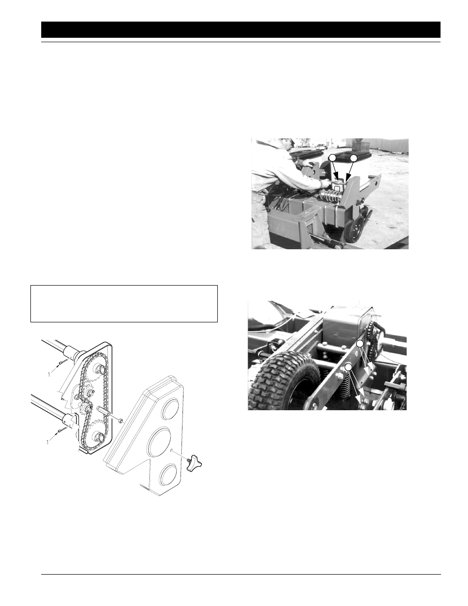
Shaft Alignment
Improper alignment of the transmission-input and -output
shafts can cause pins to shear. To function properly, the
shafts must be aligned and level. If the planter is consis-
tently shearing pins, follow these steps to check and adjust
the shafts.
1.
Check that the transmission-input shaft (1) and trans-
mission shaft (2) are aligned. Remove cotter pin from
coupler sleeve. Pull the coupler sleeve back and ob-
serve the shafts.
16832
2
1
Transmission-Input Shaft Alignment
Figure 7-4
2.
If the shafts are not aligned, adjust the contact-drive
tower. Loosen the mounting bolts (1) on both sides of
tower. Adjust tower position until shafts are aligned.
16849
1
1
Contact Drive Housing Adjustment
Figure 7-5
3.
Retighten tower mounting bolts. Slide coupler sleeve
over transmission-input shaft and re-insert cotter pin.