Finger pickup meter – Great Plains PT1230 AA1062 Operator Manual User Manual
Page 47
45
Section 7 Maintenance and Lubrication
PT1230 Pull-Type Folding Planter 401-069M-A
10/10/12
Great Plains Mfg., Inc.
4.
Level the transmission-output shaft. Place a straight
edge across the 7-by-7-inch frame tube. Take a mea-
surement from the straight edge (1) down to the top of
the shaft (2). Repeat measurement at each row unit.
Measurements must be equal across the planter.
To level the shaft, loosen the shaft hanger bearings (3)
at each row unit. Adjust shaft until measurements are
equal across the planter.
16833
1
2
3
Leveling Transmission-Output Shaft
Figure 7-7
Finger Pickup Meter
Inspect and repair the finger pickup meter by removing the
2 bolts holding the meter to the hopper. Remove the 3
bolts on the meter baffle to gain access to the finger mech-
anism.
Rotate the meter input shaft by hand to check the fingers.
The fingers should be against the carrier plate in closed
area and raised in open area as shown in Figure 7-8.
Finger Raised/Location of Brush
Figure 7-8
12353
Inspect the brush for wear. The brush should cover at least
1/2 of the finger pickup tab. Replace every 100 acres of
row operation, see Figure 7-8 for location.
Chaff and debris can build-up in the meter preventing
proper functioning of the fingers. Clean every 50 hours of
operation.
To clean the corn meter:
1.
Remove the cotter pin, lock nut, and adjusting nut
from the shaft.
2.
Lift the finger assembly off the shaft and clean.
3.
Replace worn finger assembly by lifting the finger out
of the slot. Average life expectancy of these parts
should be 250-300 acres of row operation. When fin-
gers are replaced, the open end of the spring loop
should be toward the inside of the finger housing.
4.
Inspect the indentations in the carrier plate for wear.
Replace carrier plate when wear to the plate becomes
excessive or the seeding accuracy will be affected.
5.
Reassemble the meter in reverse order. Be sure the
fingers are installed correctly so the finger housing is
flush with the carrier plate. If the finger housing is not
flush with the carrier plate, make sure that the projec-
tion on the cam is in the notch on the bearing housing.
The meter will not function properly if the projection is
not in the notch.
6.
With the finger assembly against the plate, tighten the
adjusting nut until it is snug. Then turn an additional
1/3 turn. Turn the meter by hand making certain that
the meter is not over tightened. Proper meter resis-
tance would be 22-25 in/lbs of torque applied at the
meter input shaft.
7.
Install the cage nut and the cotter pin.
8.
Install the baffle and attach the meter to the hopper.
IMPORTANT: Check tightness of the adjusting nut
on the meter after the first day and periodically there-
after.
Check the belt on the meter periodically.
Use these steps:
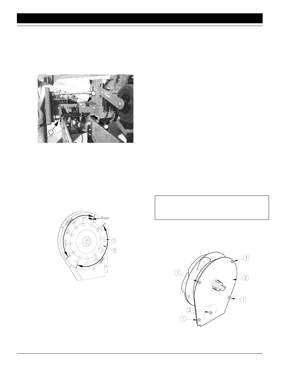
1.
Remove the 4 bolts (#1) located on the belt housing,
the bolt holding the belt roller and the belt housing
cover (#2). See Figure 7-9.
Finger Meter Belt Removal
Figure 7-9
14966