Closing wheel offset, Closing disk adjustments, Closing disk tube shield – Great Plains PT1230 AA1062 Operator Manual User Manual
Page 30: Liquid fertilizer adjustments
28
Section 4 Adjustments
10/10/12
PT1230 Pull-Type Folding Planter 401-069M-A
Great Plains Mfg., Inc.
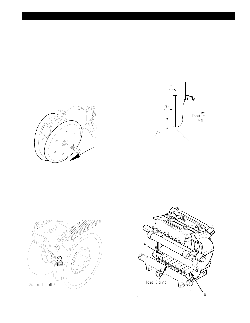
Closing Wheel Offset
The 1x12 wheels can be offset to help prevent trash from
plugging the closing wheels. If the closing wheels are not
offset, the wheels should be located in the front holes of
the press wheel arm.
To offset the wheels, do as follows:
1.
Raise planter slightly to remove weight on the closing
wheels.
2.
Remove the bolt holding the wheel, see
Figure 4-11.
3.
Move the wheel to the rear hole and attach with the
bolt. Tighten the bolt to the correct torque value listed
in the Torque Values Chart for Common Bolt Sizes in
“Appendix” on page
Closing Disk Adjustments
The closing disk options consists of two disks and a
6 1/2 x 12 press wheel. The disk down pressure can be ad-
justed to provide closing of the seed trench.
To select one of four down pressure settings, ratchet the
spring cam to the next cam height by turning the head of
the support bolt clockwise. Refer to Figure 4-12.
Closing Wheel & Offset
Figure 4-11
12347
Closing disk & Tube Holes
Figure 4-12
15830
Closing Disk Tube Shield
To prevent clogging in insecticide hoses:
1.
Clamp closing disk tube shield to closing disk with
hose clamp provided.
2.
Insert insecticide hose (#1) inside the closing disk
tube shield (#2) as shown. When unit is picked up, the
insecticide hose should be about 1/4” above the bot-
tom of the shield.
Liquid Fertilizer Adjustments
If ‘A’ or ‘B’ hose (end hoses) should run off the back, re-
align hoses as follows:
1.
‘A’ Hose - Loosen hose clamp on intake manifold and
twist hose 1/4 turn in a counter-clockwise direction.
2.
‘B’ Hose - Loosen hose clamp on intake manifold and
twist hose 1/4 turn in a clockwise direction.
3.
Retighten hose clamp.
Closing Disk Tube Shield
Figure 4-13
15717
Hose Alignment
Figure 4-14
12402