Tool bar heights – Great Plains NTA3007 Operator Manual User Manual
Page 150
146
NTA907 or NTA3007
Great Plains Manufacturing, Inc.
166-371M
2012-07-02
Tool Bar Heights
Tool bar heights must be checked and adjusted in
representative field conditions, with openers lowered to
planting height, and pulled forward in the ground, as for
section alignment checking above. New drills are
shipped with the wing eye bolts not fully tightened. They
must be set before first planting.
9.
Check that rows are fully lowered, running level, and
that centre front and wing gauge wheels are not
running light. Adjust down-pressure and weight
transfer as needed (page 101).
If rows are not running level, adjust sub-frame shims
as needed (page 106).
Refer to Figure 157 (shown with wings folded for clarity)
10. Check opener sub-frame tool bar height at the centre
section. Measure from the average soil surface level
to the bottom of the rear opener tool bar.
The distance should be:
76.2 cm (30 inches).
Refer to Figure 158
11. Check sub-frame tool bar height at the inside and
outside ends of the wing rear tool bar. If either end
differs from centre height by more than about
6 mm (
1
⁄
4
inch), adjust the eye bolt
above the
parallel arms at that end.
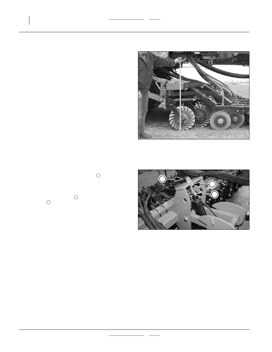
12. To adjust an eye bolt:
Back the upper jam nut
up a few turns. Adjust the
lower nut
. The adjustment is about
2.8 mm (0.11 inch) of opener height per turn of the
adjuster nut.
Whether adjusted or not, secure the size 1-8 jam nut
to torque specification (page 167).
13. Check and set all four (4) wing ends and eye bolts.
14. Pull forward and re-check height.
Figure 157
Checking Tool Bar Height
29519
Figure 158
Adjusting Wing Tool Bar Height
29520
3
1
2
1
2
3