Control valve overview, 2w c t, Tc w b 1 – Great Plains NTA3007 Operator Manual User Manual
Page 107
Great Plains Manufacturing, Inc.
Adjustments
103
2012-07-02
166-371M
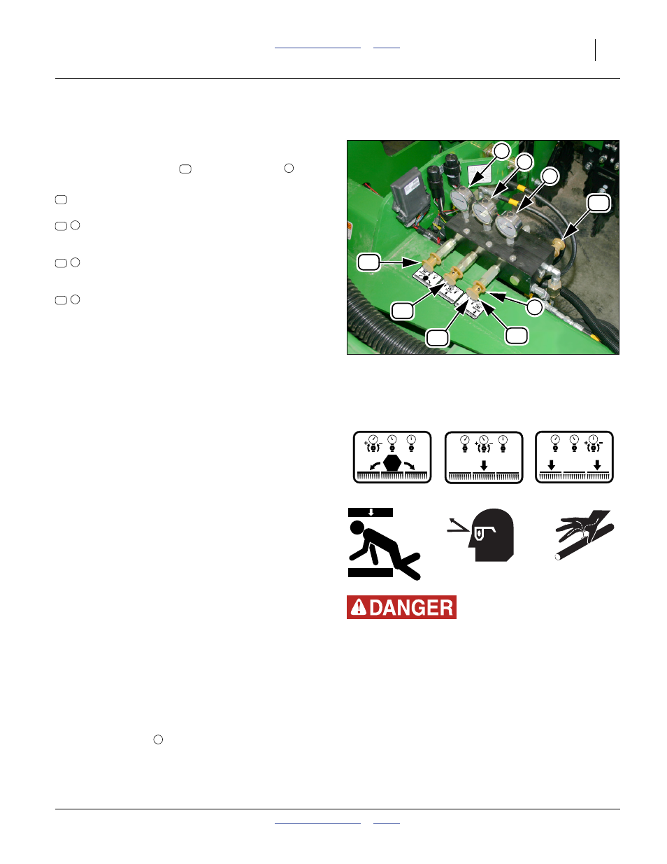
Control Valve Overview
Refer to Figure 101
There is one flow control, and three pressure controls.
Each pressure control has a gauge. All of the controls
have an adjustment knob
and a locking disc
to fix
the chosen setting.
These controls must be set and adjusted prior to first
field use of the drill. They require re-adjustment when
there are significant changes in field conditions.
1.
Unfold (page 34) and lower (page 42) drill. Put
tractor in Park and set tractor parking brake.
2.
Lock hydraulic lever forward during field operation for
constant hydraulic flow to openers.
John Deere tractors with Sound-Gard™ Body:
Use lever lock clip, John Deere part number R52667,
to lock lever forward. See your tractor dealer for clip
purchase and installation.
John Deere 7000 Series tractors: Rotate valve
detent selector to motor position to lock lever in
forward position.
John Deere 8000 Series tractors: Set timer to
continuous. Push lever forward until detent clicks.
Case-IH Magnum™ tractors: Lock lever forward in
detent position. You may need to turn up detent
pressure to its maximum setting. Do not tie hydraulic
lever past detent position with a strap. See your
tractor dealer for hydraulic-system details.
Other tractors: Lock lever forward in detent position.
You may need to turn up detent pressure to
maximum or use a mechanical detent holder to hold
lever forward. See your tractor dealer for proper
means of providing constant flow to openers
3.
At bypass valve
, release locking disc and close
bypass valve for no oil flow by turning knob clockwise
completely.
Bypass valve (normally closed),
adjusted on tractors with “LS closed” hydraulics
,
Centre section down-pressure,
sets the force applied to all centre section rows,
and may be set higher than wings
,
Wing down-pressure,
sets the force applied to all wing rows, and may
be set lower than the centre section.
,
Transfer of weight from centre to wings,
sets the weight available to the wings. At higher
wing down-pressures, it is possible for the rows to
lift the wings, unless weight is transferred.
Figure 101
Down-Pressure Valve Block
29422
Wing Weight
Transfer
Centre Down
Pressure
Wing Down
Pressure
848 397C-A
1000-2400
848-396C-A
700-2100
848 395C-A
800-2200
2
w
c
t
Crushing and High Pressure Fluid Hazards:
This adjustment requires working near the unfolded and
lowered drill with the hydraulic system active. Assign two
people to this task, one in the tractor cab, ready to shut the
tractor down on a hand signal from the observer or upon any
unplanned event.
T
C
W
B
1
1
2
B
C
c
W w
T
t
B