Levelling drill, Section alignment, Levelling drill section alignment – Great Plains NTA3007 Operator Manual User Manual
Page 149
Great Plains Manufacturing, Inc.
Maintenance and Lubrication
145
2012-07-02
166-371M
Levelling Drill
Wing alignment and sub-frame heights are adjustable.
Frame heights are not adjustable. Centre height is fixed
by the front transport wheels. Wing height is fixed by the
centre section height and the wing gauge wheels.
Section Alignment
1.
Move the drill to representative field conditions.
Unfold and lower.
2.
Set hitch height as described at See “Heights and
Levelling” on page 32.
3.
Pull forward with rows in ground. Stop. Leave rows in
ground.
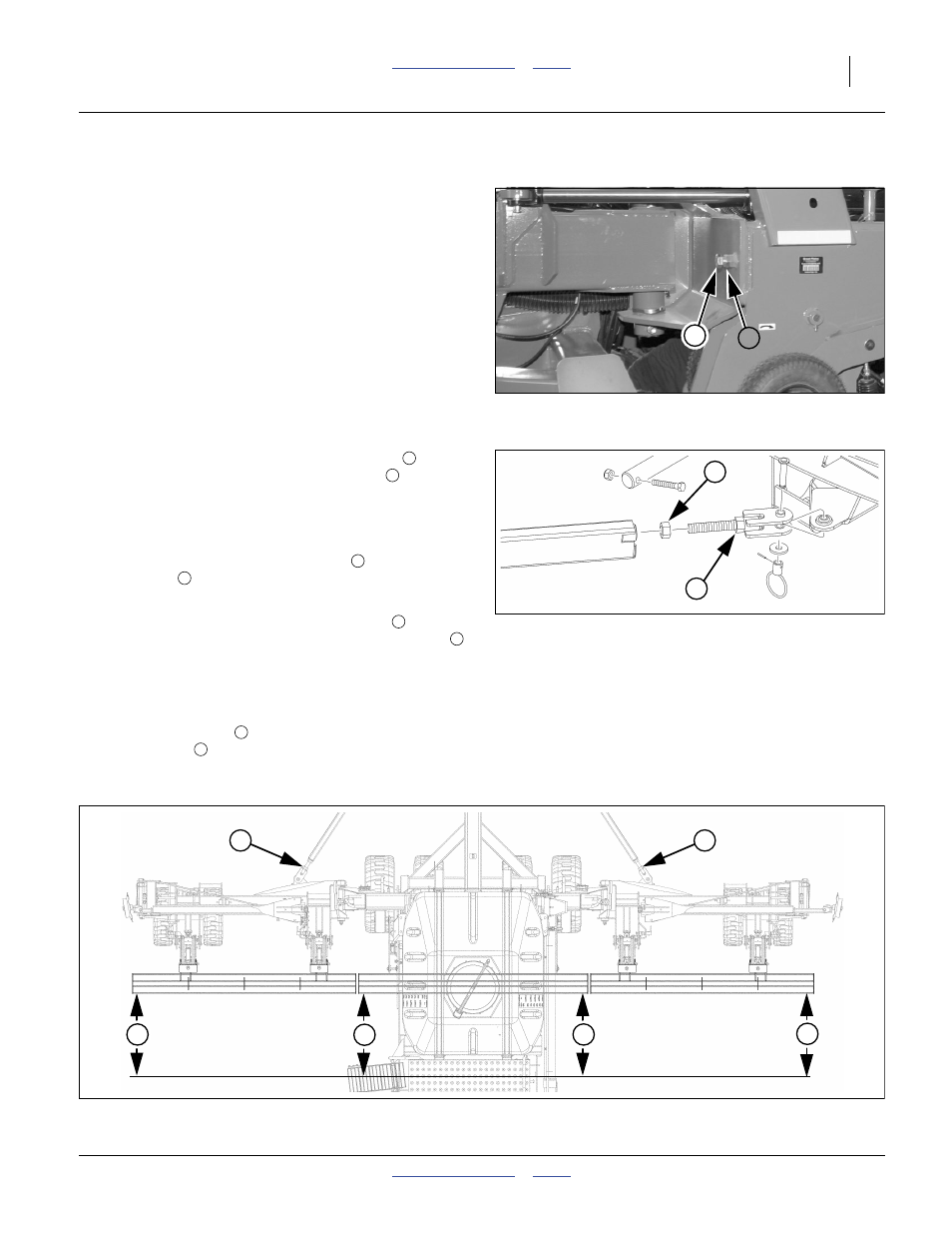
Sight along the rear face of the rear opener tool bar.
Measure the wing end position (dimension
)
relative to the centre section (dimension
).
5.
If the wings are even with the centre, or less than
25 mm (1 inch) ahead, no adjustment is necessary.
Loosen wing fold stop bolt jam nuts
, and fully seat
stop bolts
.
To adjust a wing lead, loosen the jam nut
at the
pull bar for that side, and rotate the turnbuckle nut
to move the wing forward or back.
The effect of the turnbuckle is to move the wing tip by
about 6 mm (
1
⁄
4
inch) per full turn.
8.
Back out stop bolt
until it contacts wing. Secure
with jam nut
. Re-tighten jam nuts and align other
side as needed.
Figure 154
Wing Stop Bolt
29694
3
4
Figure 155
Wing Pull-Bar Turnbuckle
29378
5
6
1
2
3
4
5
6
4
3
Figure 156
Section Alignment Check
29524
1
2
2
1
6
6