Contact drive adjustment, Contact spring force, Contact shaft up-limit – Great Plains NTA3007 Operator Manual User Manual
Page 101
Great Plains Manufacturing, Inc.
Adjustments
97
2012-07-02
166-371M
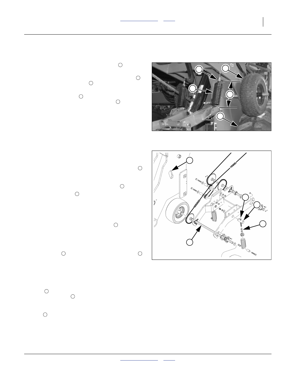
Contact Drive Adjustment
Refer to Figure 94 and Figure 95
There are two contract drive tension springs
on each
side of the drill; four total. If there seems to be:
• insufficient traction between the contact drive tires
and the main transport tires
;
• excess spring force at contact tires, or
• or a contact drive shaft
is below the minimum
clearance when raised in the frame slots
,
then follow these steps:
1.
Check tire size and inflation (page 166).
Use tire sizes specified by Great Plains, at
recommended pressures. The remaining steps of
this section cannot be used to compensate for
incorrect sizes and/or inflation.
2.
Move drill to a hard surface area, so that openers do
not lower below ground level.
Contact Spring Force
It may be necessary to loosen and move the jam nuts
for this adjustment. Re-check jam nut adjustment in any
case, as force adjustment changes up-limit.
3.
Raise openers, to fully compress springs
.
4.
Measure the length
of the springs between any
two convenient points that encompasses all turns of
the spring windings, such as from the centerline of
the lower cross-bolt to the top of the casting.
5.
Lower openers to ground.
6.
Re-measure spring length. Adjust bolt
until spring
length when lowered is 2.5 cm (1 inch) longer than
when fully compressed (as measured at step 4).
7.
If reducing force, make sure that at least 7 turns of
bolt threads are in spring casting. Check exposed
length of bolt
between bottom of spring anchor
and top of casting (not to top of jam nuts). The
maximum length of exposed thread is
91 mm (3.6 inch).
Contact Shaft Up-Limit
8.
With openers raised, at each ground drive, rotate the
shaft
and check the gap between the shaft and
the top of the slot
. There must be at least
10 mm (0.4 inch) clearance.
9.
To adjust the shaft up-limit, loosen all four jam
nuts
in the spring assembly. Rotate the upper jam
nut to set the upper limit of shaft travel. Adjust for
12 mm (0.47 inch) or more slot clearance, and equal
clearance on both sides of each ground drive arm
assembly. Secure upper jam nut with lower.
Figure 94
Contact Drive Springs
29591
2
7
3
6
1
1
2
3
4
5
Note: With openers lowered in the field, spring extension
will be more than 2.5 cm (1 inch). The setup
procedure accounts for this.
Figure 95
Contact Drive and Slot
29379
6
5
4
8
9
6
1
7
8
8
9
4
5
6